Introduction
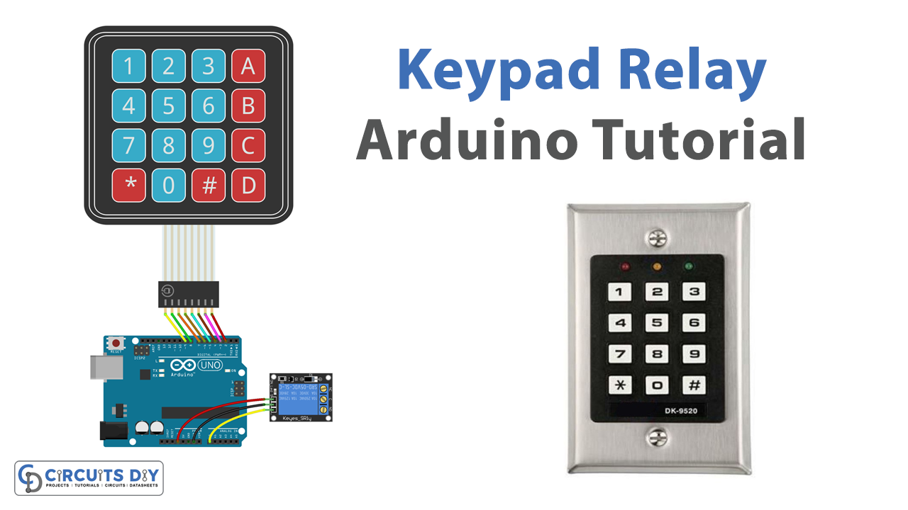
A password-controlled 5V SPDT relay using a 16-key 4×4 membrane switch keypad and an Arduino UNO microcontroller is a powerful and versatile system that can be used for a wide range of applications. This system allows for remote control of a relay, which can be used to turn on or off electrical devices or circuits. By using a keypad to input a password, the system provides an added layer of security, ensuring that only authorized individuals can control the relay.
The SPDT (Single Pole Double Throw) relay is a commonly used type of relay that has three terminals: one for the signal, one for ground, and one for VCC. The 5V voltage level means that it is designed to be used with low-voltage systems, making it an ideal choice for a wide range of projects.
Hardware Components
You will require the following hardware for Interfacing Keypad Relay with Arduino.
| S.no | Component | Value | Qty |
|---|---|---|---|
| 1. | Arduino UNO | – | 1 |
| 2. | USB Cable Type A to B | – | 1 |
| 3. | Keypad | – | 1 |
| 4. | Relay | – | 1 |
| 5. | Power Adapter for Arduino | 9V | 1 |
| 6. | Jumper Wires | – | 1 |
Keypad Relay with Arduino
- Connect the 16-key 4×4 membrane switch keypad to the Arduino UNO microcontroller. Use the pin numbers provided in the keypad’s documentation and connect them to the corresponding digital pins on the Arduino.
- Connect the SPDT relay to the Arduino. The relay should have three pins: one for the signal, one for the ground, and one for VCC. Connect the signal pin to a digital pin on the Arduino, the ground pin to GND, and the VCC pin to 5V.
- In the Arduino IDE, import the Keypad library by going to Sketch > Include Library > Keypad.
- Declare the keypad and the relay pins in the setup() function.
#include <Keypad.h>
const byte ROWS = 4; //four rows
const byte COLS = 4; //four columns
char keys[ROWS][COLS] = {
  {'1','2','3','A'},
  {'4','5','6','B'},
  {'7','8','9','C'},
  {'*','0','#','D'}
};
byte rowPins[ROWS] = {9, 8, 7, 6}; //connect to the row pinouts of the keypad
byte colPins[COLS] = {5, 4, 3, 2}; //connect to the column pinouts of the keypad
Keypad keypad = Keypad( makeKeymap(keys), rowPins, colPins, ROWS, COLS );
int relayPin = 13;
- In the loop() function, use the keypad.getKey() method to read input from the keypad. Compare the input to a predefined password and use the digitalWrite() function to control the relay based on the password match.
void loop(){
  char key = keypad.getKey();
  if (key == '1234') {
    digitalWrite(relayPin, HIGH);
    Serial.println("Relay On");
  } else {
    digitalWrite(relayPin, LOW);
    Serial.println("Relay Off");
  }
}
- Upload the code to the Arduino UNO microcontroller and open the Serial Monitor to check the status of the relay.
Schematic
Make connections according to the circuit diagram given below.

Wiring / Connections
| Arduino | Relay | 4X4 Keypad |
|---|---|---|
| 5V | VCC | |
| GND | GND | |
| A0 | INP | |
| D2 | R1 | |
| D3 | R2 | |
| D4 | R3 | |
| D5 | R4 | |
| D6 | C1 | |
| D7 | C2 | |
| D8 | C3 | |
| D9 | C4 |
Installing Arduino IDE
First, you need to install Arduino IDE Software from its official website Arduino. Here is a simple step-by-step guide on “How to install Arduino IDE“.
Installing Libraries
Before you start uploading a code, download and unzip the following libraries at /Progam Files(x86)/Arduino/Libraries (default), in order to use the sensor with the Arduino board. Here is a simple step-by-step guide on “How to Add Libraries in Arduino IDE“.
Code
Now copy the following code and upload it to Arduino IDE Software.
#include <Keypad.h>
#define RELAY_PIN  A0 // the Arduino pin, which connects to the IN pin of relay
#define ROW_NUM    4  // four rows
#define COLUMN_NUM 4  // four columns

char keys[ROW_NUM][COLUMN_NUM] = {
  {'1', '2', '3', 'A'},
  {'4', '5', '6', 'B'},
  {'7', '8', '9', 'C'},
  {'*', '0', '#', 'D'}
};

byte pin_rows[ROW_NUM] = {9, 8, 7, 6}; //connect to the row pinouts of the keypad
byte pin_column[COLUMN_NUM] = {5, 4, 3, 2}; //connect to the column pinouts of the keypad

Keypad keypad = Keypad( makeKeymap(keys), pin_rows, pin_column, ROW_NUM, COLUMN_NUM );

const String password_1 = "ABC1234"; // change your password here
const String password_2 = "5642B";  // change your password here
const String password_3 = "9765";   // change your password here
String input_password;

void setup() {
  Serial.begin(9600);
  input_password.reserve(32); // maximum password size is 32, change if needed
  pinMode(RELAY_PIN, OUTPUT); // initialize pin as an output.
  digitalWrite(RELAY_PIN, LOW);
}

void loop() {
  char key = keypad.getKey();

  if (key) {
    Serial.println(key);

    if (key == '*') {
      input_password = ""; // reset the input password
    } else if (key == '#') {
      if (input_password == password_1 || input_password == password_2 || input_password == password_3) {
        Serial.println("The password is correct, turning ON relay");
        digitalWrite(RELAY_PIN, HIGH);
      } else {
        Serial.println("The password is incorrect, try again");
      }

      input_password = ""; // reset the input password
    } else {
      input_password += key; // append new character to input password string
    }
  }
}
Working Explanation
The setup() function is used to initialize the microcontroller and set any necessary configurations. In this case, the setup() function is used to initialize the serial monitor, set the pin mode for the relay pin, and initialize the keypad by creating a keymap and specifying the rows and columns pins of the keypad.
The loop() function is used to control the flow of the program and read input from sensors and other devices. In the code for a password-controlled 5V SPDT relay, the loop() function reads input from the keypad using the keypad.getKey() method, which returns the character of the key that was pressed. The input is then compared to a predefined password. If the input matches the predefined password, the code uses the digitalWrite() function to turn on the relay by sending a high signal to the relay pin and sending a message “Relay On” to the serial monitor.
Applications
- Home Automation
- Industrial Control
- DIY Projects
- Access Control
- Power Control
- Security Systems
Conclusion.
We hope you have found this Keypad Relay Circuit very useful. If you feel any difficulty in making it feel free to ask anything in the comment section.