Introduction
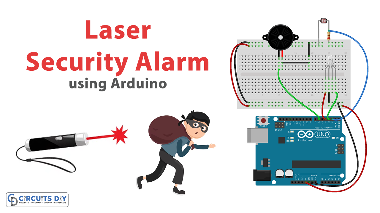
A laser security alarm system using an Arduino Uno microcontroller, an LDR sensor, and a laser light module is a highly effective and customizable security system that can be used to protect a variety of areas. This system uses a laser beam and an LDR sensor to detect any changes in the light level and triggers an alarm if someone enters the protected area and interrupts the laser beam. With the ability to adjust the threshold value and customize the system to fit specific needs, this type of security system can provide reliable protection for homes, businesses, and other areas that require a high level of security.
By using an Arduino Uno microcontroller and simple coding, this system can be easily set up and configured, making it an accessible and cost-effective security solution for anyone looking to protect their property.
Hardware Components
You will require the following hardware for the laser security alarm.
| Components | Value | Qty |
|---|---|---|
| Arduino UNO | – | 1 |
| LDR | – | 1 |
| RGB LED | ||
| Resistor | 10KΩ | 1 |
| Breadboard | – | 1 |
| Jumper Wires | – | 1 |
Arduino Code
- Set up the input and output pins:
void setup() {
  pinMode(2, INPUT_PULLUP); // set pin 2 as input with a pull-up resistor
  pinMode(3, OUTPUT); // set pin 3 as output
  pinMode(4, OUTPUT); // set pin 4 as output
  pinMode(6, OUTPUT); // set pin 6 as output
  Serial.begin(9600); // initialize the serial communication
}
- Read the input pin and print its value to the serial monitor:
void loop() {
  int m = digitalRead(2); // read the digital value of pin 2
  Serial.println(m); // print the value to the serial monitor
  delay(100); // wait for 100 milliseconds
- Check the value of the input pin and control the output pins accordingly:
if (m == 1) { // if pin 2 is HIGH
digitalWrite(3, HIGH); // turn on pin 3
digitalWrite(4, LOW); // turn off pin 4
digitalWrite(6, LOW); // turn off pin 6
delay(500); // wait for 500 milliseconds
} else { // if pin 2 is LOW
digitalWrite(3, LOW); // turn off pin 3
digitalWrite(4, HIGH); // turn on pin 4
digitalWrite(6, HIGH); // turn on pin 6
delay(500); // wait for 500 milliseconds
}
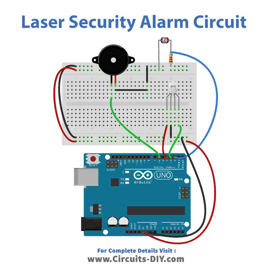
}Schematic
Make connections according to the circuit diagram given below.
Installing Arduino IDE
First, you need to install Arduino IDE Software from its official website Arduino. Here is a simple step-by-step guide on “How to install Arduino IDE“.
Code
Now copy the following code and upload it to Arduino IDE Software.
void setup() {
  // put your setup code here, to run once:
pinMode(2, INPUT_PULLUP);
pinMode(3, OUTPUT);
pinMode(4, OUTPUT);
pinMode(6, OUTPUT);
Serial.begin(9600);
}
void loop() {
  // put your main code here, to run repeatedly:
int m = digitalRead(2);
Serial.println(m);
delay(100);
if(m==1)
{
  //Serial.print("LASER ON");
  digitalWrite(3, HIGH);
digitalWrite(4, LOW);
digitalWrite(6, LOW);
  delay(500);
  }
else
{
 // Serial.print("LASER OFF");
  digitalWrite(3, LOW);
digitalWrite(4, HIGH);
digitalWrite(6, HIGH);
  delay(500);
  }
}
Working Explanation
The code sets up four pins in the setup() function: pins 2, 3, 4, and 6. Pin 2 is set as an input pin with an internal pull-up resistor enabled using the INPUT_PULLUP argument. Pins 3, 4, and 6 are set as output pins. In the loop() function, the code reads the state of pin 2 using digitalRead() function and stores the value in the variable m. The state of pin 2 is printed to the Serial Monitor using the Serial.println() function with a delay of 100ms.
If the value of m is 1, which means the input pin is HIGH, the code sets pins 3, 4, and 6 to specific states to turn on a laser for a duration of 500ms. The laser is turned on by setting pin 3 to HIGH and pins 4 and 6 to LOW. If the value of m is not 1, the laser is turned off by setting pin 3 to LOW and pins 4 and 6 to HIGH for a duration of 500ms.
Applications
- Home security
- Office Security
- Perimeter security
- Museum and gallery security
- Automotive security
- Industrial security