Introduction
A Door sensor-controlled LED is a device that allows indirect control over the functionality of a light fixture using a simple door sensor. When the door is opened, the sensor sends a signal to the Arduino UNO microcontroller, which then triggers the LED to turn on. When the door is closed, the sensor sends a different signal to the Arduino UNO microcontroller, triggering the LED to turn off.
The Arduino UNO microcontroller acts as the “brain” of the device, processing the signals from the door sensor and controlling the LED accordingly. The door sensor and LED can be connected to the Arduino UNO using jumper wires and a breadboard, or by soldering them directly to the microcontroller’s pins.
Hardware Components
You will require the following hardware for Door Sensor LED with Arduino.
| S.no | Component | Value | Qty |
|---|---|---|---|
| 1. | Arduino UNO | – | 1 |
| 2. | USB Cable Type A to B | – | 1 |
| 3. | Door Sensor | – | 1 |
| 4. | Power Adapter for Arduino | 9V | 1 |
| 5. | LED | – | 1 |
| 6. | Resistor | 220Ω | 1 |
| 7. | Breadboard | – | 1 |
| 8. | Jumper Wires | – | 1 |
Door Sensor LED with Arduino
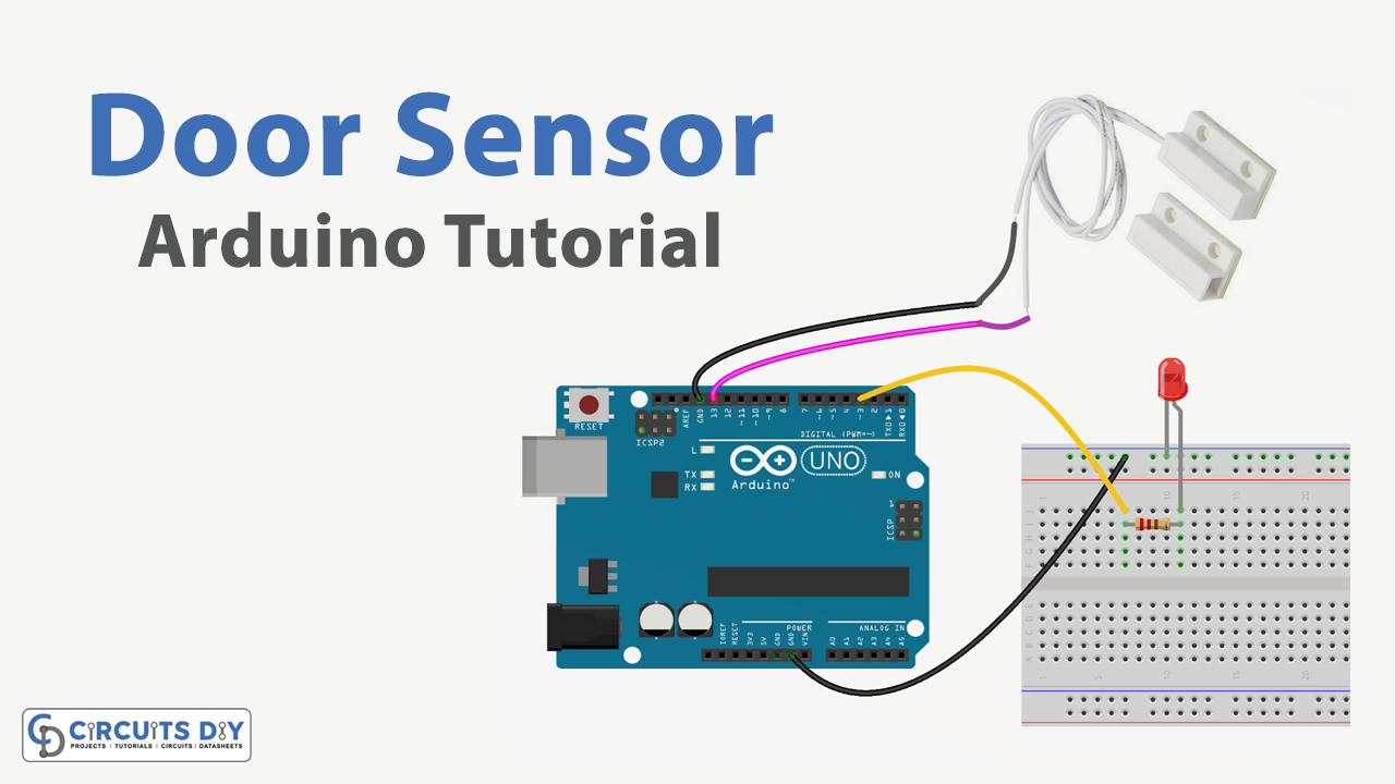
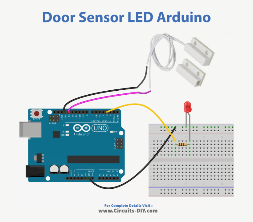
- Connect the door sensor to the Arduino. The door sensor has three pins: VCC, GND, and OUT. Connect the VCC pin to 5V on the Arduino, GND to GND, and OUT to a digital input pin (e.g. pin 2).
- Open the Arduino IDE and create a new sketch.
- Declare constants for the digital input pin and LED pin. For example:
const int doorSensorPin = 2;
const int ledPin = 13;- In the setup function, initialize the LED pin as an output and the door sensor pin as an input.
void setup() { pinMode(ledPin, OUTPUT);
pinMode(doorSensorPin, INPUT); }- In the loop function, read the state of the door sensor using digitalRead. If the door sensor is open (HIGH), turn the LED on using digitalWrite. If the door sensor is closed (LOW), turn the LED off.
void loop() {
int doorState = digitalRead(doorSensorPin);
if (doorState == HIGH) {
digitalWrite(ledPin, HIGH); }
 else {
digitalWrite(ledPin, LOW); }
}- Upload the sketch to the Arduino.
- When the door sensor is open, the LED should turn on. When the door sensor is closed, the LED should turn off.
Schematic
Make connections according to the circuit diagram given below.
Wiring / Connections
| Arduino | Door Sensor |
|---|---|
| D13 | VCC |
| GND | GND |
Installing Arduino IDE
First, you need to install Arduino IDE Software from its official website Arduino. Here is a simple step-by-step guide on “How to install Arduino IDE“.
Code
Now copy the following code and upload it to Arduino IDE Software.
const int DOOR_SENSOR_PIN  = 13; // Arduino pin connected to the OUTPUT pin of door sensor
const int LED_PIN          = 3;  // Arduino pin connected to LED's pin

int doorState;

void setup() {
  Serial.begin(9600);                     // initialize serial
  pinMode(DOOR_SENSOR_PIN, INPUT_PULLUP); // set arduino pin to input pull-up mode
  pinMode(LED_PIN, OUTPUT);               // set arduino pin to output mode
}

void loop() {
  doorState = digitalRead(DOOR_SENSOR_PIN); // read state

  if (doorState == HIGH) {
    Serial.println("The door is open");;
    digitalWrite(LED_PIN, HIGH); // turn on LED
  } else {
    Serial.println("The door is closed");
    digitalWrite(LED_PIN, LOW);  // turn off LED
  }
}
Working Explanation
A Door sensor-controlled LED using an Arduino UNO microcontroller works by using a door sensor to detect the opening and closing of a door. The door sensor sends a digital signal to the Arduino UNO microcontroller, which processes the signal and determines whether the door is open or closed. Based on this information, the microcontroller can then control the state of an LED connected to it.
The program would also make use of a delay function to pause for a certain amount of time before repeating the coding process. This delay is necessary to allow the sensor and LED to stabilize between readings and to prevent the coding sequence from executing too quickly.
Applications
- Home security system
- Automatic door opener
- Smart office or home automation
- Elevator control
- Vehicle detection in a parking lot or garage
- Automatic gate control
- Security alarm system
Conclusion.
We hope you have found this Arduino – Door Sensor – LED Circuit very useful. If you feel any difficulty in making it feel free to ask anything in the comment section.