Introduction
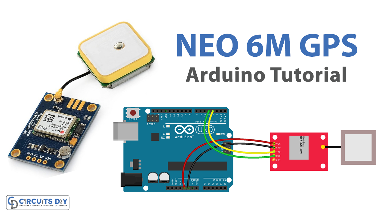
Interfacing a NEO 6M GPS module with an Arduino UNO allows you to incorporate location-tracking functionality into your Arduino projects. The NEO 6M GPS module is a popular GPS module that can provide accurate location data for your Arduino projects. By using the Serial Communication protocol, you can easily connect the GPS module to your Arduino board and access GPS data such as latitude, longitude, altitude, speed, and time. With this data, you can build a variety of location-based projects, such as GPS-based navigation systems, geo-fencing applications, and more. In this way, interfacing a NEO 6M GPS module with an Arduino UNO can greatly expand the capabilities of your Arduino projects.
The NEO-6M GPS module uses a 50-channel u-blox 6 positioning engine with high sensitivity and tracking capabilities, enabling it to work even in areas with weak GPS signal reception. It communicates with the Arduino or other microcontrollers via a serial interface using the NMEA (National Marine Electronics Association) protocol. The module features a built-in ceramic patch antenna and an EEPROM for storing configuration settings, making it easy to use and customize for various applications. The NEO-6M GPS module operates at a default baud rate of 9600 bps, but this can be changed using configuration commands.
Hardware Components
You will require the following hardware for Interfacing GPS with Arduino.
| S.no | Component | Value | Qty |
|---|---|---|---|
| 1. | Arduino UNO | – | 1 |
| 2. | USB Cable Type A to B | – | 1 |
| 3. | GPS module | NEO-6M | 1 |
| 4. | Power Adapter for Arduino | 9V | 1 |
| 5. | Jumper Wires | – | 1 |
Steps Interfacing GPS with Arduino UNO
- First, two libraries are included: the TinyGPS++ library for parsing GPS data, and the SoftwareSerial library for serial communication with the GPS module.
#include <TinyGPS++.h>
#include <SoftwareSerial.h>
- Next, the pins for the SoftwareSerial object are defined. The NEO-6M GPS module is connected to the Arduino Uno’s digital pins 3 (RX) and 4 (TX) for serial communication.
const int RXPin = 3, TXPin = 4;
- The baud rate for the GPS module is set to 9600, which is the default baud rate for the NEO-6M GPS module.
const uint32_t GPSBaud = 9600;
- A TinyGPSPlus object is created to store and parse GPS data, and a SoftwareSerial object is created to communicate with the NEO-6M GPS module using the RXPin and TXPin defined earlier.
TinyGPSPlus gps;
SoftwareSerial gpsSerial(RXPin, TXPin);
- In the
setup()function, the serial communication with the computer is initiated at 9600 bits per second, and the serial communication with the GPS module is initiated at the GPSBaud defined earlier.
Serial.begin(9600);
gpsSerial.begin(GPSBaud);
- A message is printed to the serial monitor to indicate that the program has started.
Serial.println(F("Arduino - GPS module"));
- In the
loop()function, the program waits for incoming GPS data from the GPS module.
if (gpsSerial.available() > 0) {
- When data is received, it is passed to the TinyGPS++ object for parsing.
if (gps.encode(gpsSerial.read())) {
- If the parsed data includes a valid location, the latitude, longitude, and altitude are printed to the serial monitor.
if (gps.location.isValid()) {
    Serial.print(F("- latitude: "));
    Serial.println(gps.location.lat());

    Serial.print(F("- longitude: "));
    Serial.println(gps.location.lng());

    Serial.print(F("- altitude: "));
    if (gps.altitude.isValid())
        Serial.println(gps.altitude.meters());
    else
        Serial.println(F("INVALID"));
} else {
    Serial.println(F("- location: INVALID"));
}
- The speed and date & time data are also printed to the serial monitor if they are valid.
Serial.print(F("- speed: "));
if (gps.speed.isValid()) {
    Serial.print(gps.speed.kmph());
    Serial.println(F(" km/h"));
} else {
    Serial.println(F("INVALID"));
}

Serial.print(F("- GPS date&time: "));
if (gps.date.isValid() && gps.time.isValid()) {
    Serial.print(gps.date.year());
    Serial.print(F("-"));
    Serial.print(gps.date.month());
    Serial.print(F("-"));
    Serial.print(gps.date.day());
    Serial.print(F(" "));
    Serial.print(gps.time.hour());
    Serial.print(F(":"));
    Serial.print(gps.time.minute());
    Serial.print(F(":"));
    Serial.println(gps.time.second());
} else {
    Serial.println(F("INVALID"));
}
- Finally, the program checks if it has received any GPS data in the past 5 seconds. If not, it prints a “No GPS data received: check wiring” error message to the serial monitor for debugging purposes.
if (millis() > 5000 && gps.charsProcessed() < 10)
  Serial.println(F("No GPS data received: check wiring"));
Schematic
Make connections according to the circuit diagram given below.
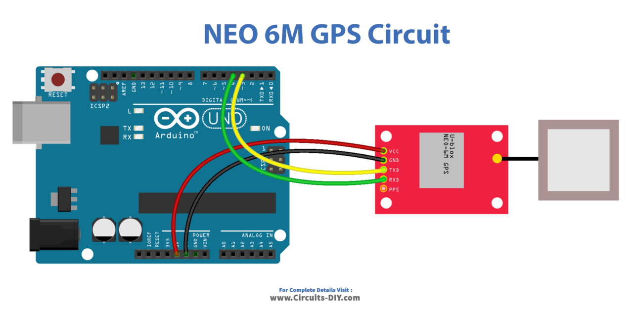
Wiring / Connections
| Arduino | Sensor |
|---|---|
| 5V | VCC |
| GND | GND |
| D3 | TXD |
| D4 | RXD |
Installing Arduino IDE
First, you need to install Arduino IDE Software from its official website Arduino. Here is a simple step-by-step guide on “How to install Arduino IDE“.
Installing Libraries
Before you start uploading a code, download and unzip the following libraries at /Progam Files(x86)/Arduino/Libraries (default), in order to use the sensor with the Arduino board. Here is a simple step-by-step guide on “How to Add Libraries in Arduino IDE“.
Code
Now copy the following code and upload it to Arduino IDE Software.
#include <TinyGPS++.h>
#include <SoftwareSerial.h>

const int RXPin = 3, TXPin = 4;
const uint32_t GPSBaud = 9600; //Default baud of NEO-6M is 9600


TinyGPSPlus gps; // the TinyGPS++ object
SoftwareSerial gpsSerial(RXPin, TXPin); // the serial interface to the GPS device

void setup() {
  Serial.begin(9600);
  gpsSerial.begin(GPSBaud);

  Serial.println(F("Arduino - GPS module"));
}

void loop() {
  if (gpsSerial.available() > 0) {
    if (gps.encode(gpsSerial.read())) {
      if (gps.location.isValid()) {
        Serial.print(F("- latitude: "));
        Serial.println(gps.location.lat());

        Serial.print(F("- longitude: "));
        Serial.println(gps.location.lng());

        Serial.print(F("- altitude: "));
        if (gps.altitude.isValid())
          Serial.println(gps.altitude.meters());
        else
          Serial.println(F("INVALID"));
      } else {
        Serial.println(F("- location: INVALID"));
      }

      Serial.print(F("- speed: "));
      if (gps.speed.isValid()) {
        Serial.print(gps.speed.kmph());
        Serial.println(F(" km/h"));
      } else {
        Serial.println(F("INVALID"));
      }

      Serial.print(F("- GPS date&time: "));
      if (gps.date.isValid() && gps.time.isValid()) {
        Serial.print(gps.date.year());
        Serial.print(F("-"));
        Serial.print(gps.date.month());
        Serial.print(F("-"));
        Serial.print(gps.date.day());
        Serial.print(F(" "));
        Serial.print(gps.time.hour());
        Serial.print(F(":"));
        Serial.print(gps.time.minute());
        Serial.print(F(":"));
        Serial.println(gps.time.second());
      } else {
        Serial.println(F("INVALID"));
      }

      Serial.println();
    }
  }

  if (millis() > 5000 && gps.charsProcessed() < 10)
    Serial.println(F("No GPS data received: check wiring"));
}
Working Explanation
In the setup() function, the serial communication is initiated at 9600 bits per second, and the GPS serial interface is initialized with the GPSBaud. A message is printed to the serial monitor for debugging purposes.
In the loop() function, the code checks if there is any data available on the GPS serial interface. If there is, it is read by the gps.encode() function, which updates the gps object. Given the location is valid, the latitude, longitude, and altitude are printed to the serial monitor. If the altitude is invalid, the “INVALID” message is printed instead. And, If the speed is valid, the speed in km/h is printed. If the date and time are valid, they are printed to the serial monitor. Finally, if no GPS data has been received after 5 seconds, a message is printed to the serial monitor to check the wiring.
Applications
- Real-time tracking of vehicles, assets, and personnel.
- Navigation systems for drones, robots, and autonomous vehicles.
- Geocaching and outdoor sports tracking.
- Weather monitoring and forecasting.
- Precision agriculture for yield mapping and crop management.
- Surveying and mapping for land use and urban planning.
- Emergency response and disaster management.
- Fitness tracking and activity monitoring.
Conclusion.
We hope you have found this GPS Circuit very useful. If you feel any difficulty in making it feel free to ask anything in the comment section.