Introduction
Doors constantly need to be opened and closed, especially in places like hotels, theaters, and shopping malls, where someone is always needed to do so. and, therefore, automatic doors are now used. You must have seen those automatic doors that get opened when there’s a person coming. Have you ever thought about which sensor they could be using? These automatic doors employ PIR sensors.
These sensors have greater applications in alarm and security systems. The name PIR is frequently used in lighting as well, and it is related to automatically turning lights on and off when someone comes close to them.
What is PIR Sensor?
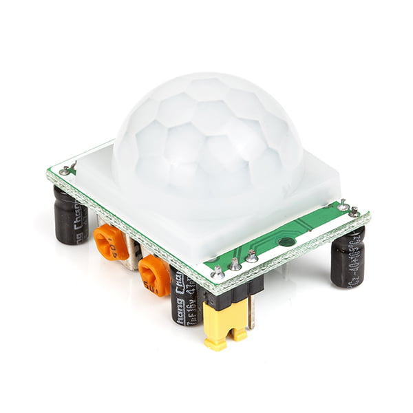
A passive infrared sensor (PIR) is a type of electronic sensor that detects motion. The sensor detects infrared (IR) light emitted by objects in its field of vision. They have mostly been employed in PIR-based motion detectors. When a human walks in the sensor’s field, the sensors sense a sudden change in infrared radiation and are triggered. It functions like a switch. It doesn’t detect or measure heat, but rather infrared radiation emitted by things.
Hardware Components
You will require the following hardware for PIR Sensor Tutorial.
| S.no | Component | Value | Qty |
|---|---|---|---|
| 1. | Arduino UNO | – | 1 |
| 2. | PIR Motion Sensor | – | 1 |
| 3. | LED | – | 1 |
| 4. | Resistor | 220Ω | 1 |
| 5. | Breadboard | – | 1 |
| 6. | Jumper Wires | – | – |
Steps Interfacing PIR Sensor
In this PIR Sensor Tutorial, we are employing very few basic electronic components. After you get those components, do follow the given steps:
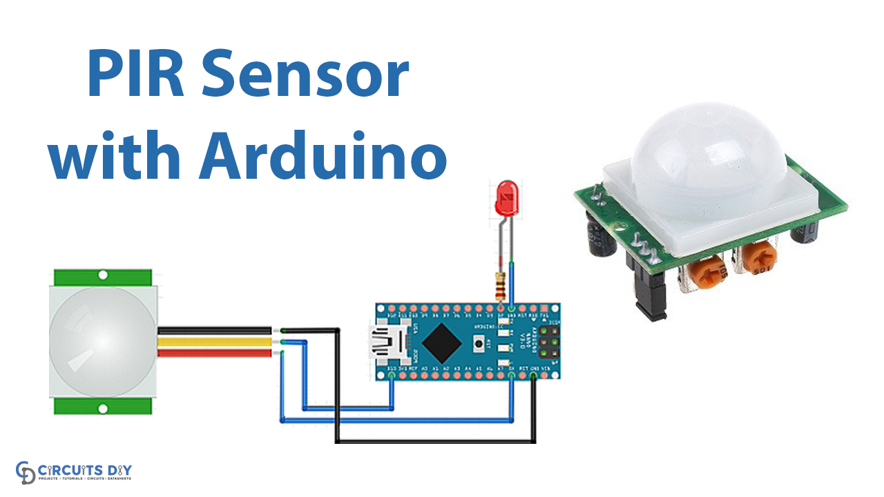
Schematic
Make connections according to the circuit diagram given below.

Wiring / Connections
| Arduino | Pir motion Sensor | LED |
|---|---|---|
| 5V | VCC | |
| GND | GND | Negative |
| D2 | OUT | |
| D13 | Positive |
Installing Arduino IDE
First, you need to install Arduino IDE Software from its official website Arduino. Here is a simple step-by-step guide on “How to install Arduino IDE“.
Code
Now copy the following code and upload it to Arduino IDE Software.
int LED = 13;             // the pin that the LED is atteched to
int PIR = 2;              // the pin that the sensor is atteched to

void setup() {
  pinMode(LED, OUTPUT);   // initalize LED as an output
  pinMode(PIR, INPUT);    // initialize sensor as an input
  Serial.begin(9600);     // initialize serial
}

void loop(){
  if (digitalRead(PIR) == HIGH) { // check if the sensor is HIGH
    digitalWrite(LED, HIGH);      // turn LED ON
    Serial.println("Motion detected!");
    delay(100);                   // delay 100 milliseconds
  }
  else {
    digitalWrite(LED, LOW);       // turn LED OFF
    Serial.println("Motion stopped!");
    delay(100);                   // delay 100 milliseconds
  }
}
Let’s Test It
It’s time to put the system to the test! If you placed something close to the PIR sensor after downloading the code and turning on the Arduino, the LED would turn on and the message would appear on the serial monitor.
Working Explanation
To understand the working of the circuit, we need to understand the coding:
- The code is quite simple. First, we define Arduino pins 2 and 13 as LED and PIR pins, respectively.
- Following, in the void setup, we specify the status of those pins; i.e. pin modes. we declare the LED pin as the OUTPUT pin and the PIR pin as the INPUT pin. We then initialize the serial monitor.
- Next, the code reads the value coming from the PIR pin and checks if it is HIGH, If the value is HIGH, it turns on the LED and prints the Motion detected on the serial monitor; otherwise, the LED remains off.
Applications
- Smart home automation systems
- Smart security systems
- Door opening and closing systems for homes, offices, or any other workplaces; etc
Conclusion
We hope you have found this PIR Sensor Tutorial very useful. If you feel any difficulty in making it feel free to ask anything in the comment section.