Introduction
Dot matrix displays—have you ever utilized them in your Arduino projects? All Arduino fans will eventually have to deal with dot matrix displays. These displays are so prevalent in today’s outdoor LED displays that they are used for nearly all types of content. Keep that in mind, in this article; we’ll be Interfacing MAX7219 LED Dot Matrix Display with Arduino UNO.
The MAX7219 is by far the best solution for controlling dot-matrix panels. It’s simple to control a single dot matrix, and many modules can be linked together for more complex projects.
What is the MAX7219 LED Dot Matrix Display?
The MAX7219 is a 16-pin display module with an 8-by-8 dot matrix, meaning there are eight pins for each row and eight for each column. All rows and columns are connected to minimize the required number of pins. We can control the complete matrix with only 16 pins by connecting rows and columns. Multiplexing is a technique for controlling multiple LEDs with a small number of control pins.

Hardware Components
You will require the following hardware.
In the hardware section, you can find all the components that are required for the MAX7219 LED Dot Matrix Display with Arduino UNO. Once you have them all, follow the given steps:
Schematic
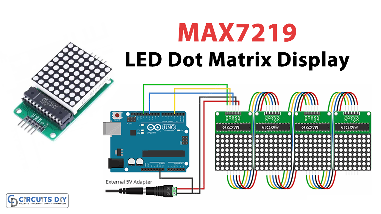
Make connections according to the circuit diagram given below.

Wiring / Connections
| Arduino | MAX7219 LED Dot Matrix Display |
|---|---|
| 5V | VCC |
| GND | GND |
| D11 | DOUT |
| D3 | CS |
| D13 | CLK |
Installing Arduino IDE
First, you need to install Arduino IDE Software from its official website Arduino. Here is a simple step-by-step guide on “How to install Arduino IDE“.
Installing Libraries
Before you start uploading a code, download and unzip the following libraries at /Progam Files(x86)/Arduino/Libraries (default), in order to use the sensor with the Arduino board. Here is a simple step-by-step guide on “How to Add Libraries in Arduino IDE“.
Code
Now copy the following code and upload it to Arduino IDE Software.
// Including the required Arduino libraries
#include <MD_Parola.h>
#include <MD_MAX72xx.h>
#include <SPI.h>

// Uncomment according to your hardware type
#define HARDWARE_TYPE MD_MAX72XX::FC16_HW
//#define HARDWARE_TYPE MD_MAX72XX::GENERIC_HW

// Defining size, and output pins
#define MAX_DEVICES 4
#define CS_PIN 3

// Create a new instance of the MD_Parola class with hardware SPI connection
MD_Parola myDisplay = MD_Parola(HARDWARE_TYPE, CS_PIN, MAX_DEVICES);

void setup() {
	// Intialize the object
	myDisplay.begin();

	// Set the intensity (brightness) of the display (0-15)
	myDisplay.setIntensity(0);

	// Clear the display
	myDisplay.displayClear();
}

void loop() {
	myDisplay.setTextAlignment(PA_LEFT);
	myDisplay.print("Left");
	delay(2000);

	myDisplay.setTextAlignment(PA_CENTER);
	myDisplay.print("Center");
	delay(2000);

	myDisplay.setTextAlignment(PA_RIGHT);
	myDisplay.print("Right");
	delay(2000);

	myDisplay.setTextAlignment(PA_CENTER);
	myDisplay.setInvert(true);
	myDisplay.print("Invert");
	delay(2000);

	myDisplay.setInvert(false);
	myDisplay.print(1234);
	delay(2000);
}
Let’s Test It
It’s now time to test the circuit. Once you wire the circuit and upload the code, the display will print: Left, center, right, invert, 1234…
Working Explanation
To understand the workings of the circuit, you need to understand the code.
- In the code, the first thing we need to do is to add all of the needed Arduino libraries.
- The MD MAX72XX library handles the LED matrix’s hardware-specific functions.
- MD Parola library handles the text effect.
- The SPI library is used to talk to the display.
- The next step is to tell what kind of hardware is being used. Since we are doing our experiments with an FC-16 module, the HARDWARE TYPE is set to FC16 HW. MAX_DEVICES is set to 4 because we are using 4 MAX7219 ICs. Next, we define the Arduino pin to which the CS pin of the display is connected.
- Then, an object of the MD Parola class is created by calling the function MD_Parola(). The hardware type is the first parameter, the CS pin is the second, and the number of MAX7219 ICs used is the third.
- In the void setup, we first use the begin() function to set up the object. The setIntensity function is used to change how bright the screen is. The function displayClear() is used to clear the screen.
- In the void loop, we first set the alignment of the text we will print using th function setTextAlignment(). We can pass the values PA LEFT, PA CENTER, and PA RIGHT to this function to align the text to the left, center, or right, respectively. MyDisplay.print is then used to print the string “Left,” “center,” “right,” and “invert,” “1234”.
Applications
- To display characters, symbols, and images in various devices and circuits.
- Indicators.
- Clocks, etc
Conclusion
We hope you have found this Interfacing MAX7219 LED Dot Matrix Display with Arduino UNO Circuit very useful. If you feel any difficulty in making it feel free to ask anything in the comment section.