Introduction
Interfacing a 4×4 Arduino membrane keypad module with a piezoelectric buzzer using an Arduino Uno is a powerful and versatile solution for creating interactive projects that require user input and sound feedback. Here, The Arduino UNO microcontroller acts as the brain of the system, it receives the input from the keypad, processes the data, and controls the piezoelectric buzzer based on the input. The Arduino Uno also allows for easy communication with the serial monitor, providing real-time feedback on the keypad input.
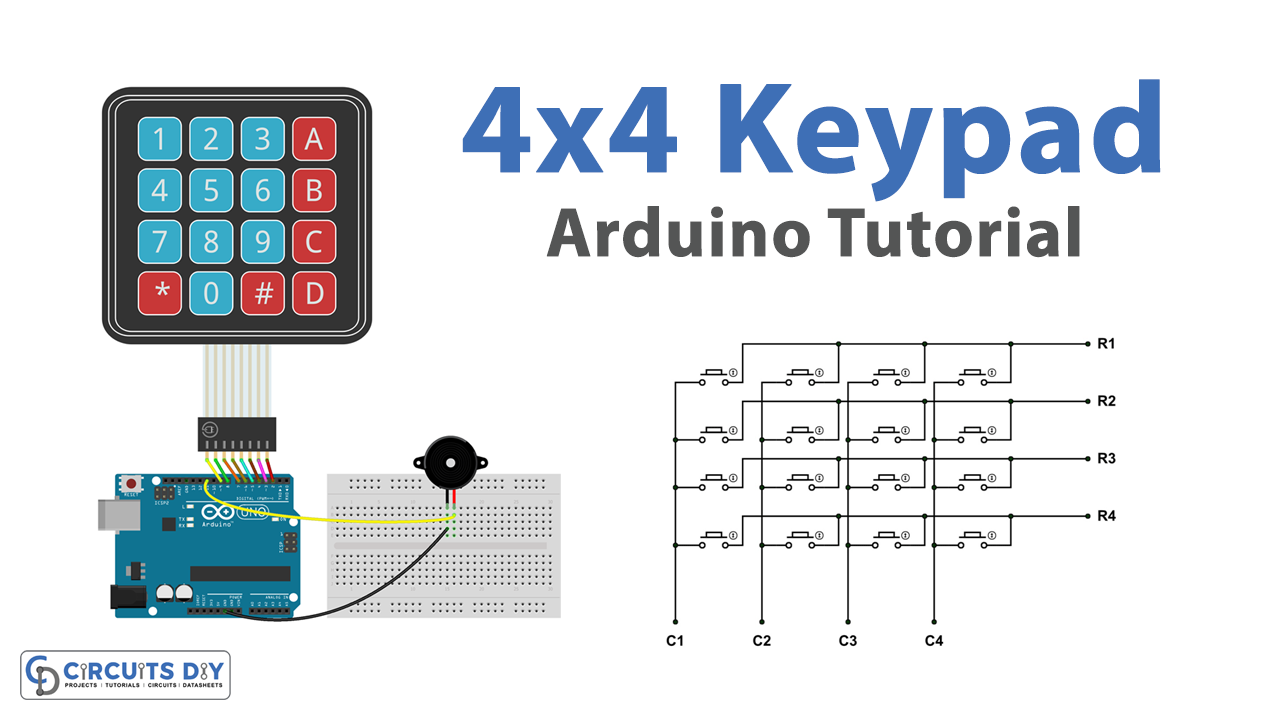
The 4×4 membrane keypad module is a user-friendly device that allows for easy input of data, it has 16 buttons arranged in a 4×4 matrix, providing a simple and efficient way for the user to interact with the project.
Hardware Components
You will require the following hardware for Interfacing Keypad with Arduino.
| S.no | Component | Value | Qty |
|---|---|---|---|
| 1. | Arduino UNO | – | 1 |
| 2. | USB Cable Type A to B | – | 1 |
| 3. | Keypad | – | 1 |
| 4. | Piezo Buzzer | – | 1 |
| 5. | Power Adapter for Arduino | 9V | 1 |
| 6. | Breadboard | – | 1 |
| 7. | Jumper Wires | – | 1 |
Keypad with Arduino
- Connect the 4×4 membrane keypad module to the Arduino Uno. Connect the rows of the keypad to pins 4, 5, 6, and 7, and the columns to pins 8, 9, 10, and 11.
- Connect the positive pin of the piezoelectric buzzer to pin 9 on the Arduino and the negative pin to GND.
- In the Arduino IDE, include the following library:
#include <Keypad.h>
- Define the row and column pins, and create a Keypad object with a keymap array and pins connected.
const byte ROWS = 4;
const byte COLS = 4;
char keys[ROWS][COLS] = {
  {'1','2','3','A'},
  {'4','5','6','B'},
  {'7','8','9','C'},
  {'*','0','#','D'}
};
byte rowPins[ROWS] = {4, 5, 6, 7};
byte colPins[COLS] = {8, 9, 10, 11};
Keypad keypad = Keypad( makeKeymap(keys), rowPins, colPins, ROWS, COLS );
- In the setup() function, initialize the serial communication and set the pin mode of the piezoelectric buzzer to output.
Serial.begin(9600);
pinMode(9, OUTPUT);
- In the loop() function, use the getKey() method to read the keypad and store it in a variable.
char key = keypad.getKey();- Use an if-else statement to control the piezoelectric buzzer. For example, if the key pressed is ‘A’, turn on the buzzer and print the key pressed to the serial monitor.
if (key == 'A') {
  digitalWrite(9, HIGH);
  Serial.println("Key Pressed: " + String(key));
} else {
  digitalWrite(9, LOW);
}
- Use a delay() function to prevent the program from reading the keypad too quickly and missing key presses.
delay(100);
- Use Serial.flush() to clear the serial buffer.
Serial.flush();
- Upload the code to the Arduino board, open the serial monitor, and set the baud rate to 9600, you should see the key pressed every time you press a button on the keypad. Also, if the key pressed is ‘A’ the piezoelectric buzzer will be turned on, otherwise, it will be turned off.
Schematic
Make connections according to the circuit diagram given below.
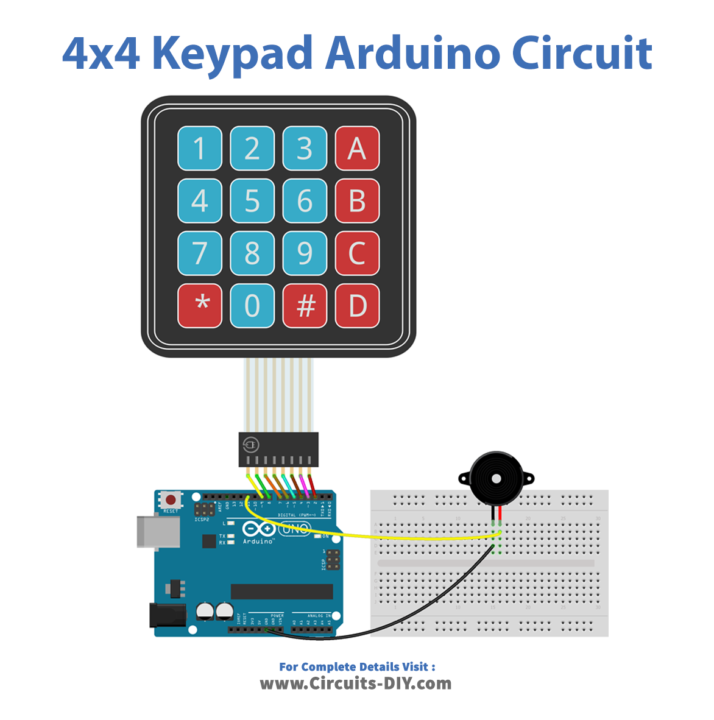
Wiring / Connections
| Arduino | Sensor |
|---|---|
| 5V | VCC |
| GND | GND |
| d2 | C4 |
| d3 | C3 |
| d4 | C2 |
| d5 | C1 |
| d6 | R4 |
| d7 | R3 |
| d8 | R2 |
| d9 | R1 |
Installing Arduino IDE
First, you need to install Arduino IDE Software from its official website Arduino. Here is a simple step-by-step guide on “How to install Arduino IDE“.
Installing Libraries
Before you start uploading a code, download and unzip the following libraries at /Progam Files(x86)/Arduino/Libraries (default), in order to use the sensor with the Arduino board. Here is a simple step-by-step guide on “How to Add Libraries in Arduino IDE“.
Code
Now copy the following code and upload it to Arduino IDE Software.
#include <Keypad.h>
#include <ezBuzzer.h>

const int BUZZER_PIN = 11;
const int ROW_NUM    = 4; // four rows
const int COLUMN_NUM = 4; // four columns

char keys[ROW_NUM][COLUMN_NUM] = {
  {'1', '2', '3', 'A'},
  {'4', '5', '6', 'B'},
  {'7', '8', '9', 'C'},
  {'*', '0', '#', 'D'}
};

byte pin_rows[ROW_NUM] = {9, 8, 7, 6};      // connect to the row pinouts of the keypad
byte pin_column[COLUMN_NUM] = {5, 4, 3, 2}; // connect to the column pinouts of the keypad

Keypad keypad = Keypad(makeKeymap(keys), pin_rows, pin_column, ROW_NUM, COLUMN_NUM );
ezBuzzer buzzer(BUZZER_PIN); // create ezBuzzer object that attach to a pin;

void setup() {
  Serial.begin(9600);
}

void loop() {
  buzzer.loop(); // MUST call the buzzer.loop() function in loop()
  char key = keypad.getKey();

  if (key) {
    Serial.print(key); // prints key to serial monitor
    buzzer.beep(100);  // generates a 100ms beep
  }
}
Working Explanation
In the code, the first step is to include the necessary library, in this case, the Keypad library, which allows the Arduino UNO to interact with the 4×4 membrane keypad module. Then, the rows and columns pins are defined, and a Keypad object is created with a keymap array that holds the keys of the keypad and the pins it is connected to.
In the setup() function, the serial communication is initialized with a baud rate of 9600, and the pin mode of the piezoelectric buzzer is set to output. In the loop() function, the getKey() method is used to read the keypad and store the pressed key in a variable. An if-else statement is then used to control the piezoelectric buzzer based on the key pressed. For example, if the key pressed is ‘A’, the piezoelectric buzzer is turned on, and the key pressed is printed to the serial monitor. If any other key is pressed, the piezoelectric buzzer is turned off.
Applications
- Quality Control
- Industrial Automation
- Automated Guided Vehicles (AGVs)
- Robotics
- Medical Equipment
Conclusion.
We hope you have found this 4×4 Keypad Circuit very useful. If you feel any difficulty in making it feel free to ask anything in the comment section.