Introduction
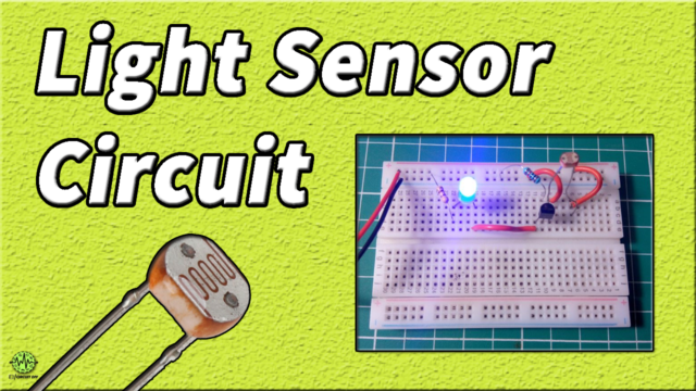
In many countries, you may have seen those electronic LED street lights which turn ON automatically after the sunset. Basically, these LED lights use LDR in their circuit. LDR, is a Light-dependent resistor, as the name implies resisting the light. Hence, resistance increases as the light intensity got increases. At dark, the circuit starts working and that’s why suitable for street light circuitry. However, the LDR circuit is also used to detect t the light level. So, in this article, we are making a flasher circuit through LDR. But, how does it works? Maybe the question arises in your mind. Well, this article is all about that. Therefore, in this tutorial, we will make and understand the working process of “LED Flasher Circuit with LDR”.
For the output, the circuit is using white LEDs. Since the blinking of lights is the major operation of this circuit, therefore, these sorts of circuits are generally used as art and for decoration purposes. For instance, they get utilized to enrich the homes at weddings, birthday parties, etc, the flasher circuit plays an artistic role.
Hardware Components
The following components are required to make LED Flasher Circuit
| S.no | Component | Value | Qty |
|---|---|---|---|
| 1. | LDR | – | 2 |
| 2. | Transistor | BC547 | 2 |
| 3. | LED | 5MM | 1 |
| 4. | Variable Resistor | 10k, 18K, 220R | 1, 1, 2 |
| 5. | Capacitor | 47uf | 2 |
BC547 Pinout

For a detailed description of pinout, dimension features, and specifications download the datasheet of BC547
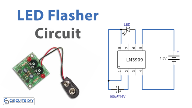
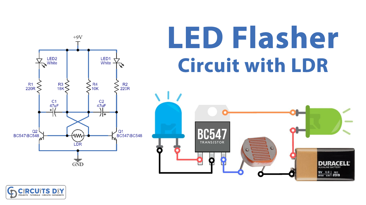
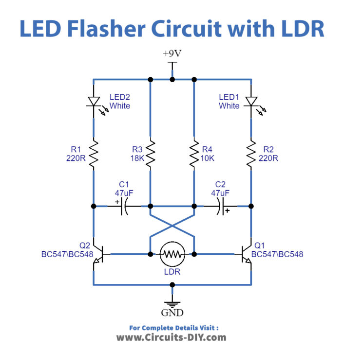
LED Flasher Circuit
Working Explanation
In this LED Flasher Circuit with LDR, when the light intensity is higher than the standard, the LDR resistor value is going to be lower. Hence, LDR works as an infinite resistor when light intensity is lower. Capacitors in the circuit also work alternatively. When one is charging, the other gets discharged, while the other gets charging, the first one discharges. Hence we can say it works like a flip flop. Capacitor C1 discharges through transistor Q2 and capacitor C2 discharges with transistor Q1. On higher light, the circuit blinks very fast, as the light goes far or intensity decreases the blinking also got decreased. Hence, in dark, there will be no blinking.
Application and Uses
- It can be used as an indicator in various circuits.
- Also, in the warning device.
- It’s a good project for beginners to understand LDR.