In this tutorial, we are going to demonstrate a TRIAC or SCR Tester circuit. TRIAC or SCR is a useful component even though it is not used in all electronic devices or circuits but they perform very essential tasks in some circuits.
TRIAC/SCR can be tested using a multimeter. It is harder to test them using different multimeters than to test them with this circuit. This circuit is a simple tester that is suitable for testing all the TRIACs and SCRs.
Hardware Components
The following components are required to make the TRIAC or SCR Tester Circuit
| S.no | Component | Value | Qty |
|---|---|---|---|
| 1. | Battery | 12V DC | 1 |
| 2. | TRIAC | BT136 | 1 |
| 3. | Switch | – | 2 |
| 4. | Resistor | 270Ω | 1 |
| 5. | Lamp | 12V | 1 |
| 6. | Connecting Wires | – | 1 |
| 7. | Breadboard | – | 1 |
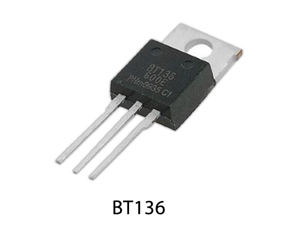
BT136 Pinout

For a detailed description of pinout, dimension features, and specifications download the datasheet of BT136
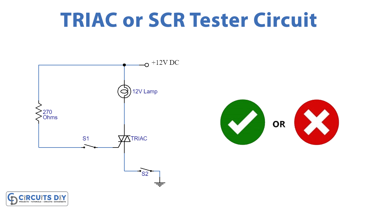
TRIAC or SCR Tester Circuit
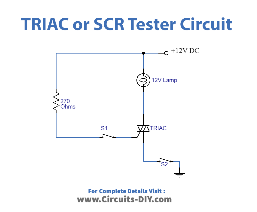
Working Explanation
This circuit is a simple arrangement for showing the basic switching action of an SCR. This can be done by connecting the SCR to the circuit as shown in the diagram and turning the Switch S2 on. The Lamp will remain off. Now when you push the switch S1 on and you will see the lamp glowing indicating the ON state of the SCR. The lamp will remain on even if the switch S1 is released. This shows that the SCR/TRIAC is working fine.
The operating voltage of this circuit is 12 volts DC. A resistor is used in this circuit to limit the current going into the Lamp.
Applications and Uses
This circuit is ideal for testing all kinds of SCRs and TRIACs.