Experimenting with electronics by making simple projects but with little innovation is fun. That’s why we always try to come up with circuits that may develop the interest of a beginner. Hence, in this article, we are making a Remote Control Switch Circuit Using 4017 IC. Remote controls are the household electronic devices used for television, air conditioning, etc. But, what if you as a beginner try to control the bulb or light in your room? Sounds good? So, let’s start making the circuit.
But, before starting let’s understand the pin configuration of IC 4017. CD4017 is a CMOS decade divider or counter, having 10 output pins, from pin 1 to pin 7 and pin 9 to pin 11. Pin 16 is for the applied voltage from 3V to 15V, while pin 8 is for the ground. Pin 13 is for the clock, when there’s logic zero, the clock gets enabled and the counter increases one count for every clock pulse. When there’s logic one, the clock input gets stopped, and the counter does nothing when the pulse arrives.
Hardware Components
The following components are required to make the Remote Control Switch Circuit
| S.no | Component | Value | Qty |
|---|---|---|---|
| 1. | IR Reciever | TSOP1738 | 1 |
| 2. | Transistors | BC547, BC556 | 1 |
| 3. | Resistor | 1k, 4.7k, 100K, 100 ohm | 1, 1, 1, 1 |
| 4. | Relay | 6v | 1 |
| 5. | LED | – | 1 |
| 6. | Electrolytic Capacitor | 100uf | 1 |
| 7. | IC | CD4017 | 1 |
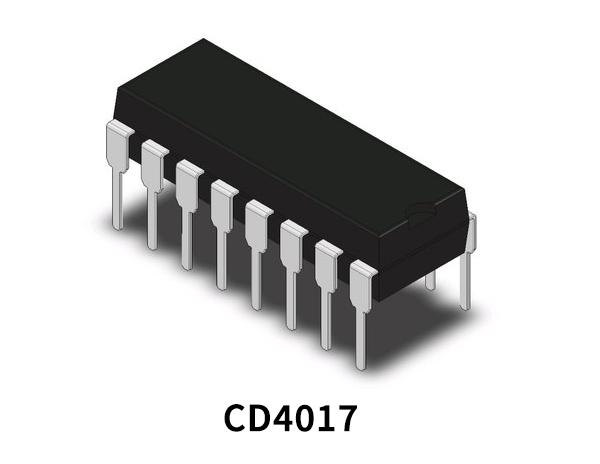
CD4017 Pinout

For a detailed description of pinout, dimension features, and specifications download the datasheet of CD4017
BC547 Pinout

For a detailed description of pinout, dimension features, and specifications download the datasheet of BC547
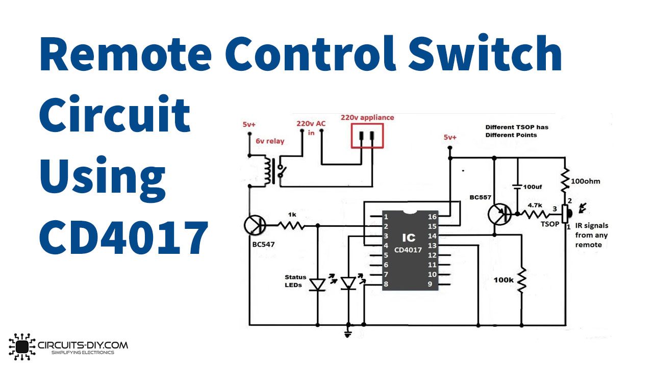
Remote Control Switch Circuit
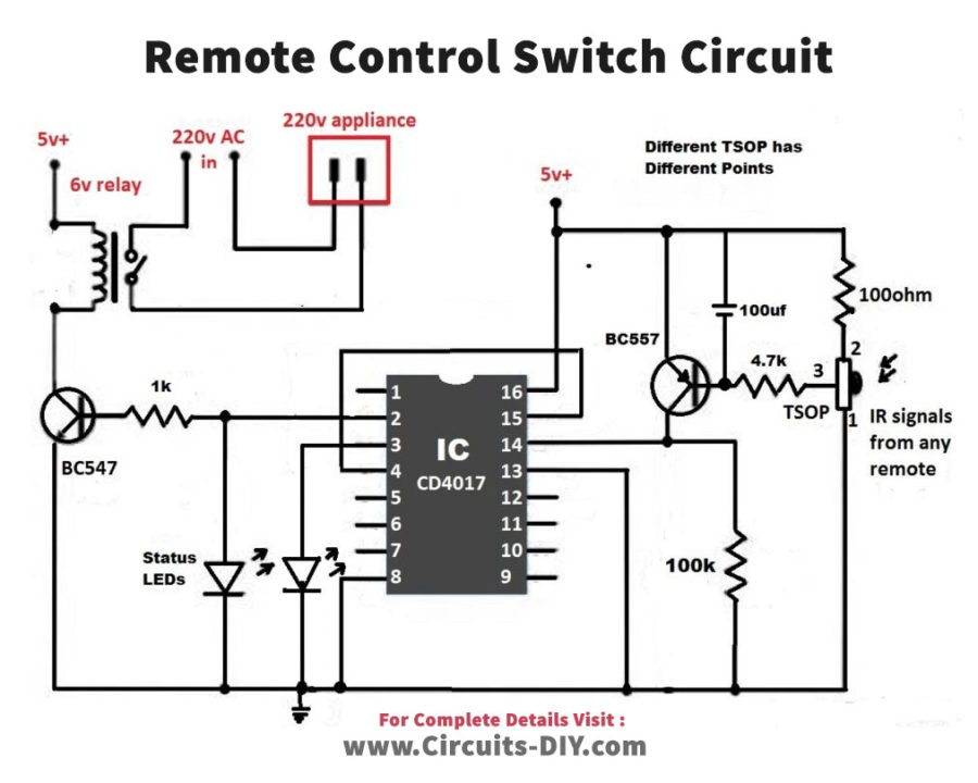
Working Explanation
The remote Control Switch Circuit includes two stages. The input stage contains the BC557 transistor, 100uf capacitor, 4.7K resistor, 100 ohms resistor, and a TSOP. TSOP is basically an IR receiver that works as a switch. It converts the IR signal into an electrical signal in the circuit. Thus, in this circuit, it does the same. It converts the coming IR signal of the remote and triggers pin 14 of the wired IC through the transistor. Therefore, at the output stage, a pulse is generated at pin 2 of the IC. which tru=iggers the BC547 transistor. The transistor turned ON the attached relay which drives the load.
Applications
- You can use this to control the appliances of your home.
- With some more advancements, it can be used in home automation circuits.