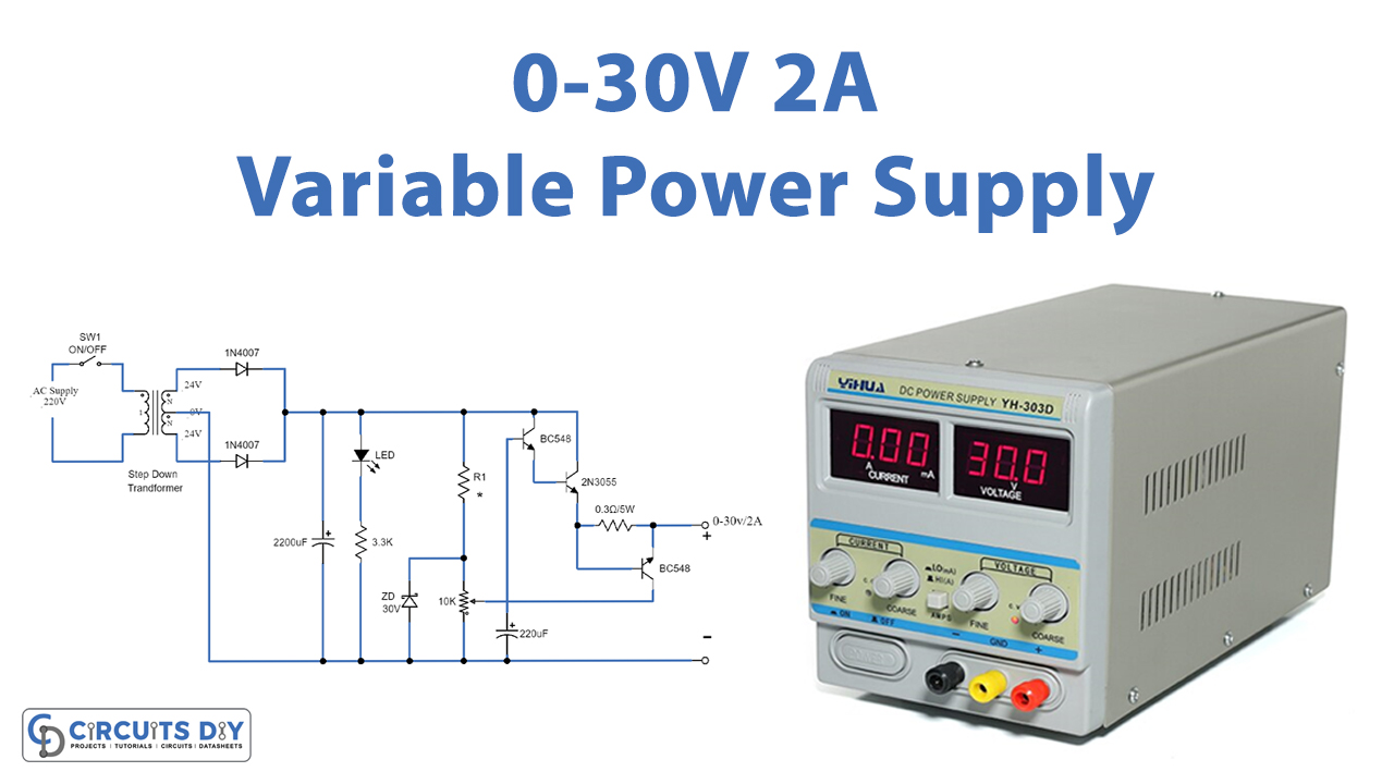
In this tutorial, we are going to make a “Simple Variable power supply circuit 0-30V 2A”.
The power supplies are an essential part of almost every electronic device. A power supply circuit is rated by the voltage or range of voltage it supplies and the maximum current it allows to draw by a load. As households are provided with AC voltages as main supplies, and a lot of electrical appliances like fans, fluorescent tubes, and others are capable of using AC voltages directly but most electronic devices require conversion of AC voltage to DC voltages for their operation.
Any external power supply circuit needs to convert AC voltage to DC voltage. It can be designed in many ways and can be adjustable or fixed. In this project, an adjustable power supply circuit is designed, which takes AC and provides 0 to 30V 2A DC Voltage as output.
Unregulated Power supply
For this purpose, we use a step-down transformer. The circuit experience some drop in the output voltage due to resistive loss. Therefore, we need a transformer of a high voltage rating greater than the required 30 V, and the transformer should provide 2A current at the output. So, The most suitable step-down transformer is 18V-0-18V/2A. This transformer step-downs the mainline voltage to 36V AC.
The stepped-down AC voltage needs to be converted into DC voltage. The rectification is the process of converting AC into DC. . In this circuit, we used a full-wave bridge rectifier for converting the 36V AC to 36V DC.
The output of the full-wave rectifier is not a steady DC voltage. It has double the frequency of main supplies but still contains ripples. Therefore, it needs to be smoothed by connecting a capacitor in parallel to the output of the full-wave rectifier. This capacitor acts as a filtering capacitor that bypasses all the AC through it to the ground. At the output, the mean DC voltage left is smoother and ripple-free.
Adjustable Reference Voltage
The power circuit should provide regulated and constant voltage without any fluctuation or variation. For voltage regulation, a linear regulator is needed in the circuit. The aim of using this regulator is to maintain a constant voltage of a desired level at the output. Some little current flows through Adjustable Reference Voltage.
In this circuit, the maximum voltage at the output should be 30V. Zener diode is perfect for voltage regulation at the output. This circuit consists of a Zener diode and a Variable resistor. It determines the output voltage level. For adjusting output voltage from 0 to 30V a variable resistor is connected. The variable probe of VR1 is connected to the collector of the BC548 switching transistor. By varying this resistor, the emitter of the switching transistor will provide the varying voltage between 0 and 30V. The Zener diodes used in the circuit must be of 1W rating otherwise, they will get damaged due to heating.
Power Transistors
The Zener diode can provide current in milliamperes only. Therefore, for deriving a high load current at the output, some linear elements must be connected in series with the load that could provide the required current. So, the most current will flow through the power transistor. It works like a large bridge for a higher current. This circuit uses an NPN bipolar junction transistor as a linear element. A Q1 transistor is used for providing sufficient base voltage to the NPN Bipolar Q2 transistor 2N3055. The 2N3055 transistor is capable of providing a 2A current at the output. The transistors are connected in a Darlington Pair Amplifier configuration to output for desired current gains. In the Darlington pair configuration, the net current gain is a multiplication of the current gains of the two transistors. And it has the controlled current lead.
Overload Protection
As the current demand will increase at the output load, the current exceeds 2A. the power transistor will start heating up. To overcome this problem, we have the overload protection section. Inside there is the resistor to check higher current and transistor to cut off the controlled current of power transistor down. And a proper heat sink must be mounted across the transistor to dissipate the excess heat. Otherwise, the transistor can blow off. And also damage other devices.
Hardware Components
The following components are required to make a Variable Power Supply Circuit
| S.no | Component | Value | Qty |
|---|---|---|---|
| 1. | Resistor | 3.3K, 100 ohms, 0.3 ohms | 1 |
| 2. | Potentiometer | 10K | 1 |
| 3. | Electrolytic Capacitor | 2,200µF, 220µF | 1 |
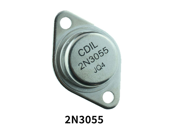
| 4. | Power Transistor | 2N3055 | 1 |
| 5. | Transistor | BC548 | 2 |
| 6. | Diode | 1N4007 | 2 |
| 7. | Zener | 30V | 1 |
| 8. | Transformer | – | 1 |
2N3055 Pinout
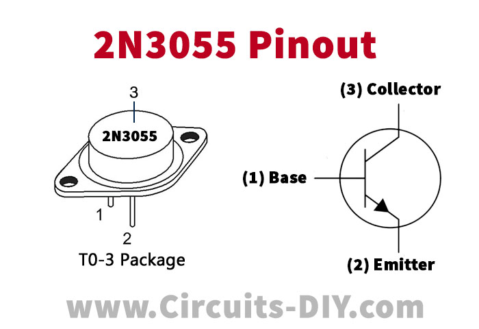
For a detailed description of pinout, dimension features, and specifications download the datasheet of 2N3055
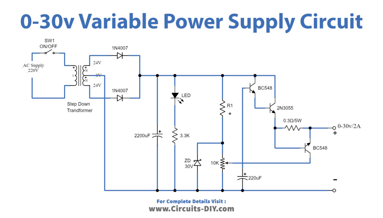
Variable Power Supply Circuit
Working Explanation
First, we supply the AC which is 220V to the transformer T1 through on/off switch SW1 and fuse F1. Fuse is used to protect the circuit from too much power source. The transformer performs two tasks. It converts the utility voltage and steps the voltage down to 24v-0v-24v according to the three tapings. It gives electrical isolation between the utility network and power supply output. This step-down voltage goes into the full-wave rectifier. The Rectifier converts the AC voltage to a DC voltage.
As we got rippled DC voltage. Capacitor C1 filters out DC voltage about 36V DC and 2A maximum. Then there is LED1 to show power on and resistor R1 limits current to a safe value. Next, the current comes to the regulating section. This filtered output goes to the input of the regulator.
The power circuit should provide regulated and constant voltage without any fluctuation or variation. Zener diode is perfect for voltage regulation at the output. R2-100ohms and ZD1-30V are connected as the 30V steady DC regulators. For adjusting output voltage from 0 to 30V a variable resistor is connected to the output. The variable probe of RV1 is connected to the collector of the BC547 switching transistor. By varying this resistor, the emitter of the switching transistor will provide the varying voltage between 0 and 30V. Now there are transistors Q1, and Q2 in Darlington mode. To drive or increase the output current up to 2A. The capacitor C2 at the output terminals of the power circuit helps in handling fast transient changes and noise at the output load. The value of this capacitor depends on the deviation in the voltage, current variations, and transient response time of the capacitor used. Also, there is short-Circuit protection included, which is by transistor Q3 and resistor R3.
Applications
This circuit can be used as a power adapter to support a wide range of electronic applications such as broadcasting, digital cameras, printers, laptops, and other portable electronic devices. It can also be used as an adjustable DC supply source for electronic devices.