Introduction
Earthquakes cause catastrophes. Not only does it destroy and harm places, but it also takes lives. Moreover, considering that we live in a time with numerous high-rise buildings, there is a higher probability they can get damaged in the earthquake events. Therefore, it is essential to take precautions. Thus, in this post, we’ll explain how to create a Simple Earthquake Detector with a Vibration Sensor & using ESP01
Because the absence of these sensors might result in significant damage, earthquake sensors are integrated into high-rise buildings. The high-rise buildings and other structures are protected from earthquake damage by the earthquake detection sensors, which detect long-period seismic motion.
What is an Earthquake Detection Sensor?
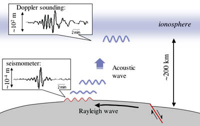
The Earthquake detector uses an electrostatic capacitive acceleration sensor produced with semiconductor micromachining technology. This system can detect ground oscillation, even for the longer vibration cycles which are also known as long-period seismic motion

JLCPCB is the foremost PCB prototype & manufacturing company in china, providing us with the best service we have ever experienced regarding (Quality, Price Service & Time).
Hardware Components
You will require the following hardware for a Simple Earthquake Detection Sensor with a Vibration Module using Arduino!!.
| S.no | Component | Value | Qty |
|---|---|---|---|
| 1. | ESP01 | – | 1 |
| 2. | Vibration Tilt Switch | – | 1 |
| 3. | LED | – | 1 |
| 4. | Resistor | 10KΩ, 220KΩ | 1,1 |
| 5. | Breadboard | – | 1 |
| 6. | Jumper Wires | – | 1 |
Steps Making Earthquake Detector
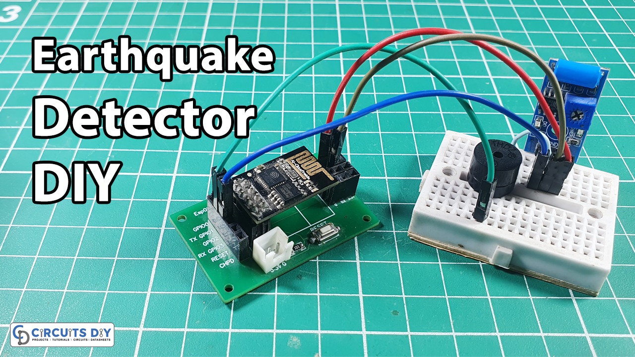
A simple Earthquake Detector with a Vibration Sensor requires very few components. All the components are listed above in the table. Once you get them, proceed as follows:
Schematic
Make connections according to the circuit diagram given below.
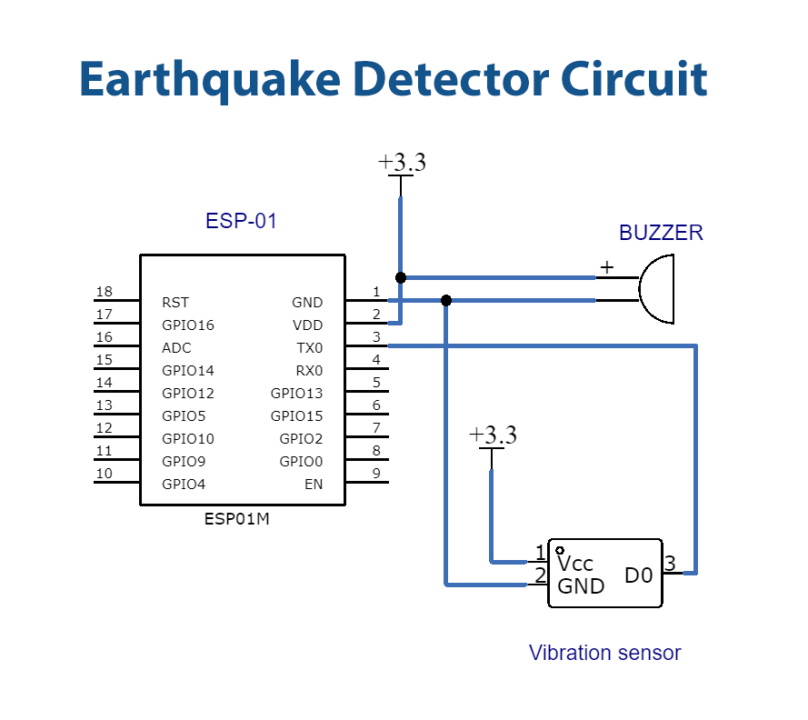
Wiring / Connections
| ESP01 | Tilt Switch | Buzzer |
|---|---|---|
| 3.3V | VCC | |
| GND | GND | -Ve |
| D2 | Dout | |
| D0 | +Ve |
Code
Now copy the following code and upload it to Arduino IDE Software.
int BUZZER = 0;      // Digital Pin 0 define Buzzer interface
int VIBRATION = 2;   // Digital Pin 2 define vibration sensor interface
int VAL;             // Define the variable as VAL
void setup()
{
Serial.begin(9600);
pinMode(BUZZER,OUTPUT); //The defined Output as Buzzer
pinMode(VIBRATION,INPUT); //The defined input as Vibration
}
void loop()
{
VAL=digitalRead(VIBRATION);
if(VAL==HIGH)        // If the sensor detects a vibration Buzzer will be HIGH
{
Serial.print("Vibration Detected : ");
Serial.println(VAL);
digitalWrite(BUZZER,HIGH);
delay(1000);
}
else
{
Serial.println(VAL);
digitalWrite(BUZZER,LOW); //if detects no vibration Buzzer stay in LOW
}
}
Let’s Test It
It’s time to test the circuit! So after uploading the code, open the serial monitor and observe the readings. When there is any vibration occurs, the buzzer will make a sound.
Working Explanation
To understand how the circuit works, let’s see how code works:
- First, we define the digital pins of the Arduino that are connected to the buzzer and the sensor. Also, we define a variable named VAL to store the values that will be read by the sensor.
- In the setup, we initialize the serial monitor.
- In the void loop, we first give the function to read the values coming from the sensor, and then we store that in VAL. After that, we give the condition that if that value is high, the buzzer makes the sound, otherwise, the Serial monitor would print the trading of VAL
Applications
- Earthquake detection systems
Conclusion.
We hope you have found this simple Earthquake Detection Sensor very useful. If you feel any difficulty in making it feel free to ask anything in the comment section.