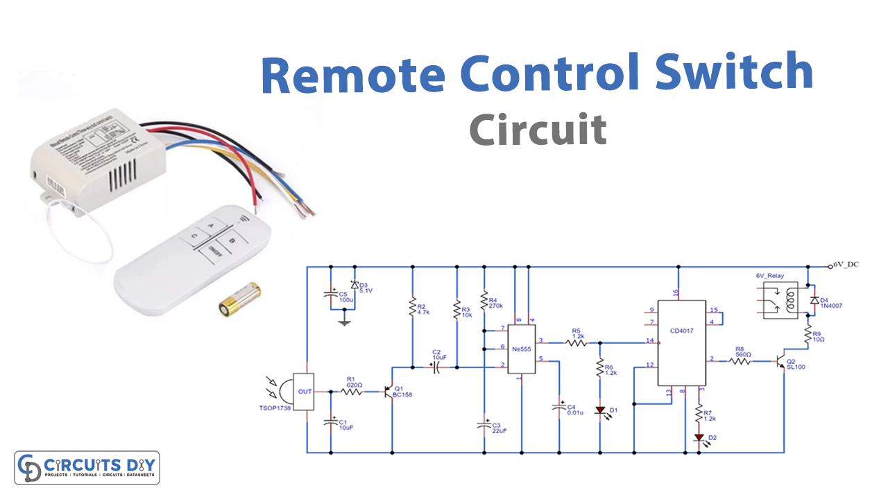
Remote controls are pretty much accessible in every home. Controlling of Air-conditions, televisions get possible by the remote control. However, not everyone is using it for other appliances and home automation. So, In this project, we will utilize the television’s remote control. And, control other appliances using it.
IC NE555 is in the multivibrator mode that produces a four-second long signal pulse. Remember, to use the remote having a 38KHz frequency. Moreover, try to solder a circuit on a good Vero board. Also, any switch can be used for this circuit. Because for any switch, the carrier frequency remains the same. And, we need only the exact carrier frequency. Make sure. to use a regulated 6 volts power supply for the circuit.
Hardware Required
| S.no | Component | Value | Qty |
|---|---|---|---|
| 1. | Vero board | – | 1 |
| 2. | IC | NE555, CD4017, TSOP1738 | 1, 1, 1 |
| 3. | Capacitors | 0.01uf, 10uf, 22uf, 100uf | 1, 1, 2, 1 |
| 4. | Resistors | 560ohms, 620ohms, 1.2K, 4.7K, 10K, 270K | 1, 1, 3, 1, 1, 1 |
| 5. | LED | – | 2 |
| 6. | Switch | – | 1 |
| 7. | Diode | 1N4007, Zener diode 5.1V | 1, 1 |
| 8. | Transistor | BC158, SL100 | 1, 1 |
| 9. | Power supply | 6V | 1 |
Circuit Diagram
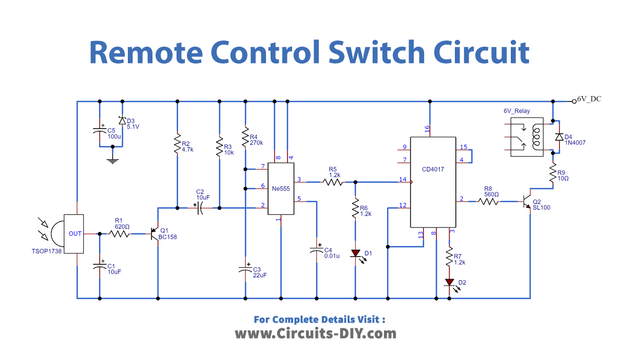
Working Explanation
IC3 is the IR remote sensor. It receives the signal. When there is no signal the output is high. Therefore, it makes the transistor Q1 OFF. When the signal of 38KHz is detected by IC3, it turns ON the transistor. Hence, a negative pulse can be seen at the output of IC1. Since this IC here works as a monostable multivibrator. Therefore, it gives a long signal. This long signal is the input clock of flip-flop IC2. Its high output at pin 2 gets amplified by the transistor and drives the relation. On the next signal, the output of this OC2 toggles the state. As a result, we get toggling on the press.
Application and Uses
It can be used for home appliances and home automation.