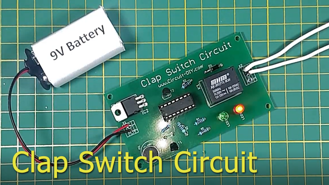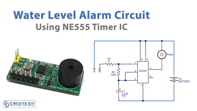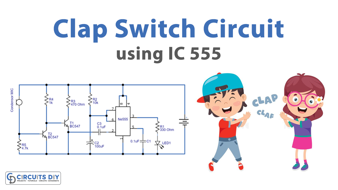
An electronic device that can control appliances by users’ clap action is a clap switch. The main advantage of this device is that it is mainly helpful for a mobility-impaired person. The condenser mic is one of the main components in the circuit that tracks the input clap sound based on the pitch of the clap and transduces this sound energy into some electric pulses. These electric pulses are the desired input to the clap switch circuit. Here we design a simple clap switch by using IC 555, this circuit makes LED glow while you clap or make louder noise.
Hardware Required
| S.no | Component | Value | Qty |
|---|---|---|---|
| 1. | IC | NE555 Timer | 1 |
| 2. | Condenser Mic | – | 1 |
| 3. | Transistor | BC547 | 2 |
| 4. | Resistor | 330Ω,10KΩ,470Ω,1KΩ,4.7KΩ, | Each One |
| 5. | Capacitor | 0.1uF,100uF | 2,1 |
| 6. | LED | – | 1 |
| 7. | Connecting Wires | – | – |
| 8. | Battery | 6V | 1 |
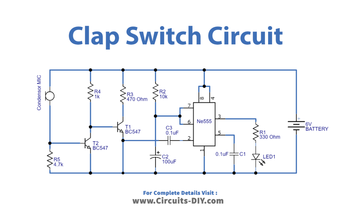
Circuit Diagram
Working Explanation
Here as we can see that the main part of the circuit is IC555 and the condenser mic. Here the condenser mic reacts as a sound sensor, this will produce voltage oscillation when the loud sound is produced. Those voltage oscillation signals are amplified by a two-stage (BC547) amplifier and given into triggering input of IC555. By receiving triggering input, the timer IC makes a mono pulse depending on the timing resistor and timing capacitor (R2, C2). Here output drives LED, we can connect buzzer or relay as required for our need. This construction will give a mono pulse when the trigger is received from the mic, the duration of pulse time varies with respect to R2 and C2 connected with IC555.
Applications
You can use this circuit sound-based concept in many ways to activate different appliances.