Introduction
If you’re a person who forgets the water motor after turning it ON. Or, if you always get busy with work that you fail to remember to turn OFF the water. Then, this circuit is definitely for you. All you need is a little knowledge of electronics and circuit design. And, also the required components. There are indeed many methods to make water level alarms. It can be made by using transistors with NE555 IC. It can also be made with Arduino, etc. But the circuit we are going to discuss here is simpler and easy to make. The circuit is also cheaper than other circuits
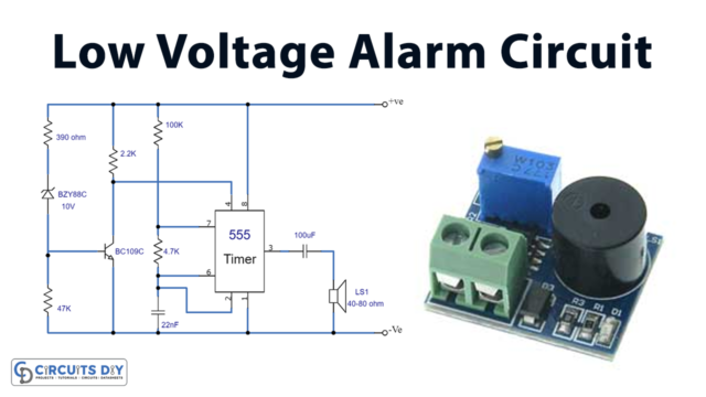
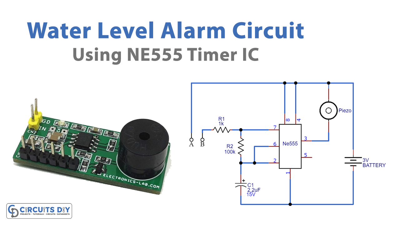
This circuit mainly uses a NE555 timer IC that’s wired as an astable multivibrator. Don’t use the circuit on a voltage greater than 3 volts. Place the probes where you want to sense the level. And, remember to use insulated copper wires as probes.
Hardware Required
| S.no | Component | Value | Qty |
|---|---|---|---|
| 1. | Breadboard | – | 1 |
| 2. | Resistor | 1K, 100K | 1, 1 |
| 3. | Capacitor | 2.2uf/15V | 1 |
| 4. | Buzzer | – | 1 |
| 5. | Battery | 3V | 1 |
| 6. | IC | NE555 Timer | 1 |
Circuit Diagram of Water level alarm
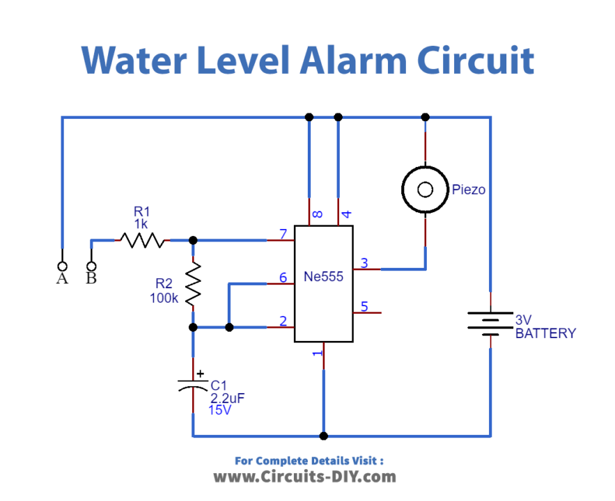
Working Explanation of Water level alarm
When the water reaches the insulated probes, some current passes through the water. IC starts producing the oscillations. The frequency of these oscillations depends on the capacitor and the resistors in the circuit. Also, it depends on the resistance of the probes. The buzzer then produces a sound to indicate that water has reached a certain level.
Application and Uses
- In simple home automation circuits
- In the industries and other related applications
- With some modification, it can be cascaded with a water motor