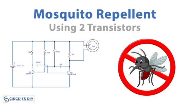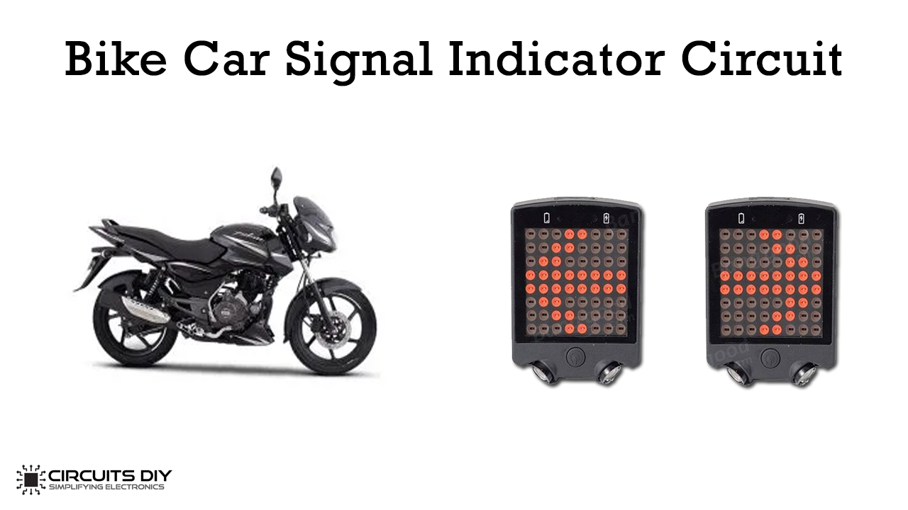
We have seen vehicles turning indicators when they turn left or right and it looks cool and can be made without any microcontroller.
So In this article, we will build a fancy car turning point indicator/bike circuit using the timer IC 555, with four bright LEDs, one by one in a particular model and we can control the speed or frequency of the LED indicator by turning a potentiometer.

Hardware Components
The following components are required to make Signal Indicator Circuit
| S.No | Component | Value | Qty |
|---|---|---|---|
| 1. | Breadboard | – | 1 |
| 2. | Battery | 9v | 1 |
| 3. | Connecting Wires | – | 1 |
| 4. | IC | Ne555 Timer | 1 |
| 5. | NPN Transistor | BC547 | 4 |
| 6. | Potentiometer | 10K | 1 |
| 7. | Resistors | 220 ohm, 1k, 10k, 68k | 4, 1, 2, 1 |
| 8. | Electrolytic Capacitor | 10uF, 220uF | 1,1 |
| 9. | Diode | 1N4148 | 2 |
| 10. | LED | 5mm | 4 |
555 IC Pinout

For a detailed description of pinout, dimension features, and specifications download the datasheet of 555 Timer
Signal Indicator Circuit
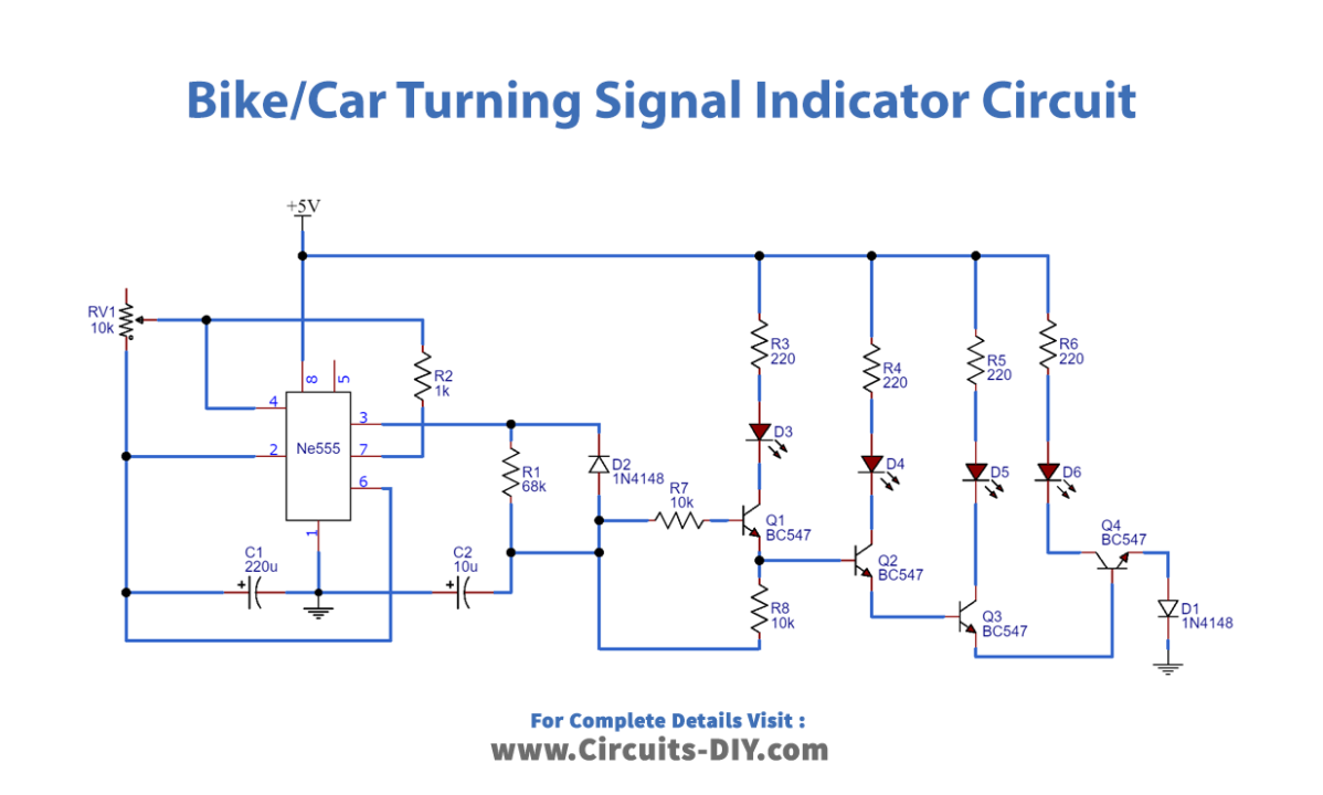
Working Explanation
In this bike turning signal indicator circuit, we used 10K and 1K resistors and a capacitor to generate a delay. It connects the 1N4148 diode in reverse bias at the output pin of the 555 timer IC to maintain a constant current. The LED is ON and OFF because of the current BC547 / MPS42A (NPN) transistor drive.
It connects the LEDs to the transistor through a 220ohm resistor relative to Vcc and may damage this saved 220ohm resistance.
This circuit indicates the left or right turn signal of the vehicle. We require two same circuits, one for the left and one for the right.
Applications
- Used to show a left turn or right turn for a motorbike or vehicle.
- We can also use this circuit as a knight LED driver circuit.
- We can give it as a gift to the children.