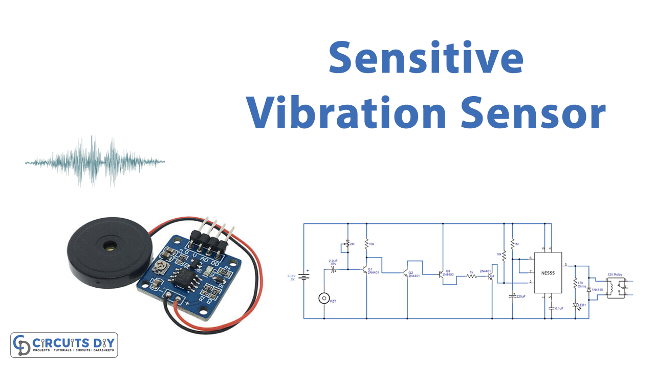
In this tutorial, we are making a super-sensitive vibration sensor switch circuit. This circuit will sense the vibration and sound around it and switch on the relay. Any AC or DC appliance connected with the relay will be switched on as well. The circuit uses a Piezoelectric sensor or piezo speaker to sense the vibration and the sound.
Piezo sensors are made up of piezoelectric ceramic material pasted in a round shape on a metal disk, these ceramic sensors generate a voltage from a few mV to almost 1 volt when they detect some vibration or a small amount of force. These piezo sensors/speakers are also used in piezo buzzers too.
Hardware Components
The following components are required to make a Sensitive Vibration Sensor Circuit
| S.no | Component | Value | Qty |
|---|---|---|---|
| 1. | DC Supply | 9-12V | 1 |
| 2. | PZT (piezo sensor) | – | 1 |
| 3. | Transistor | 2N4401, 2N3906 | 2, 1 |
| 4. | IC | NE555 timer | 1 |
| 5. | LED | – | 1 |
| 6. | Relay | 12V | 1 |
| 7. | Diode | 1N4148 | 1 |
| 8. | Resistor | 1K, 10K, 1M, 470Ω, 22K | 3, 2, 1, 1, 1 |
| 9. | Electrolytic Capacitor | 220µF, 2.20µF | 1, 1 |
| 10. | Ceramic Capacitor | 0.1µF | 1 |
NE555 IC Pinout

For a detailed description of pinout, dimension features, and specifications download the datasheet of 555 Timer
2N4401 Pinout

For a detailed description of pinout, dimension features, and specifications download the datasheet of 2N4401
2N3906 Pinout
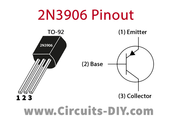
For a detailed description of pinout, dimension features, and specifications download the datasheet of 2N3906
Sensitive Vibration Sensor Circuit
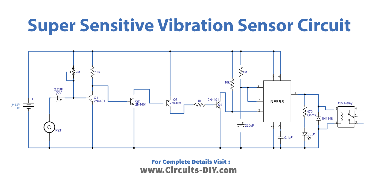
Working Explanation
This circuit can be operated from 9 to 12 volts. It is divided into five stages the first four of which are amplification through transistors and the last stage is built with a 555 timer IC. When any sound or vibration is detected by the piezo sensor it will produce a small electrical signal which is passed through the four stages for amplification through the four transistors. The last transistor will send the amplified signal to the trigger pin of the 555 timer IC and the output at pin 3 will go high.
This will activate the LED and the relay switch for a specific time period, this time period depends on the values of the capacitor used at the input of the IC. The time period can be increased or decreased by changing its value. A 2M variable resistor is used to adjust the sensitivity of the circuit.
Applications and uses
- Doorknock sensor switch
- Touch sensor
- Shock sensor switch
- Pressure sensor