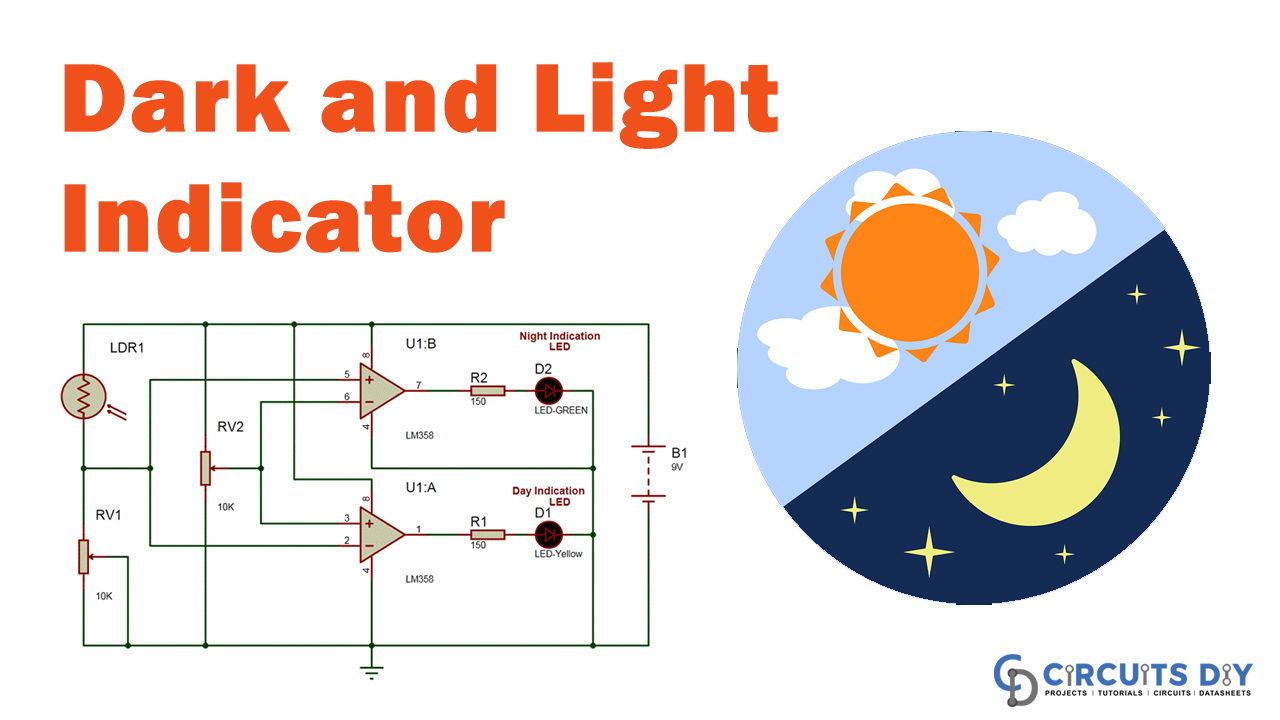
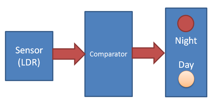
In this project, we will create a day and night indicator (or an indicator of the darkness and light) showing whether blackness or light is popular in the background. The circuit detects light through an LDR and glows the respective LED (Yellow/Green) at the output.
Hardware Component
The following components are required to make a Dark and Light Indicator Circuit
| S.no | Component | Value | Qty |
|---|---|---|---|
| 1. | IC | LM358 | 1 |
| 2. | Resistor | 150 Ohm | 2 |
| 3. | Potentiometer | 10K | 2 |
| 4. | LDR | – | 1 |
| 5. | Breadboard | – | 1 |
| 6. | Battery | 9v | 1 |
| 7. | LED | – | 2 |
| 8. | Battery Connector | – | 1 |
LM358 Pinout

For a detailed description of pinout, dimension features, and specifications download the datasheet of LM358
Dark and Light Indicator Circuit
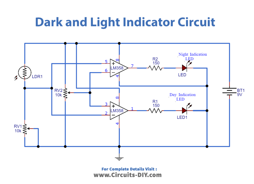
Circuit Operation
Two LM358 dual comparator ICs have been used in this circuit to estimate the voltages from differential resistive and LDR. Comparator U1:B is also known as a non-inverting mode, and 10K is attached to the inverting terminal; Comparator U2:A is configured as an inverting mode non-inverting terminal linked to the same potentiometer. An LDR is used to produce images or darkness from a 10K voltage source concerning the ground.
And the LDR and resistance midway point link directly to U1:A inverting terminal and the U1:B comparator non-inverting terminal. A red lead at the output pin for the U1 comparator bounded: B attaches to the night indicator, and a yellow LED connects to the day indicator output pin. For powering the device, a 9-volt module is used. In the above dark and light indicator circuit database, the rest of the connections can be seen.
Meanwhile this circuit, we have indicated reference voltages for both comparators by using the potentiometer. On the contrary mode, both comparators are designed. This means that only one LED lights up at the moment. It generates a positive output of another 0 volts in non-inverting mode if positive tension crosses the reference intensity to its not-investing screw. And when we use the same voltage on its flipping pin in inverting mode, it gives it a positive voltage of 0 volts on the output pin. The opposite performance occurs for both setups.
In this circuit, reference voltages have been developed by the potentiometer for both endpoints. The two comparators are constructed in contrast mode. Ensures, at one moment, that only one LED is lit. It produces a positive non-inverting output from another 0 volts when the positive voltage reaches its non-investing torque’s reference amplitude. And it gives it 0 volts positive voltage on the output pin when we use the same voltage on the reversing pin. In both conditions, the opposite performance results.
Applications and Uses
This system is typically used for automatic lighting control, cross-border light control, day and night, etc.