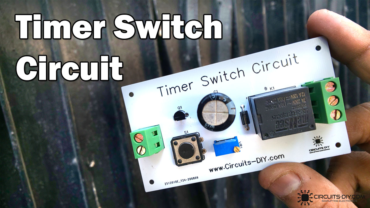
With the constant growth of the process control industry, the need and applications for On/Off delay timers is ever increasing. There are many industrial processes and tasks that would not be possible without the application of Relay based Timer Switches. A Relay based timer switch is a process control device that starts or ends a process with respect to the preset time defined by the RC time constant of the circuit.
It is generally used in controlling commercial or industrial-grade equipment such as HVAC equipment, traffic lighting, and large pumps. In today’s tutorial, we will design a 12V Relay based Timer Switch Circuit Using a BC547 Transistor & a small number of other components.
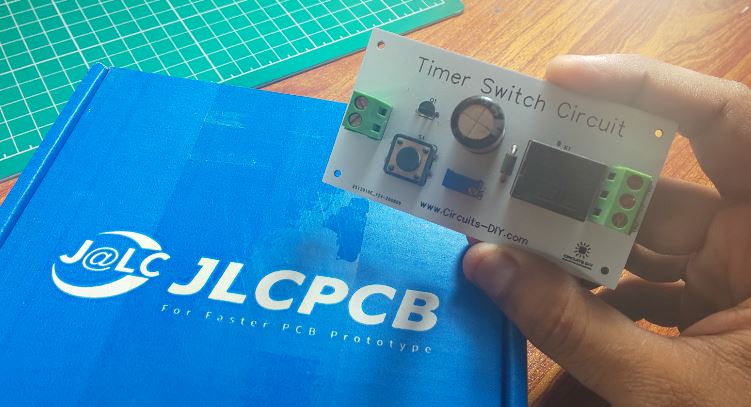
JLCPCB is the foremost PCB prototype & manufacturing company in china, providing us with the best service we have ever experienced regarding (Quality, Price Service & Time).
Hardware Components
The following components are required to make Timer Switch Circuit
| S.no | Component | Value | Qty |
|---|---|---|---|
| 1. | Relays | SPDT/5V | 1 |
| 2. | AC – DC Converter | 220V/12V | 1 |
| 3. | Transistor | BC547 | 1 |
| 3. | Block Connector | – | 1 |
| 4. | Potentiometer | 10K | 1 |
| 5. | Pushbutton | – | 1 |
| 6. | Capacitor | 1000uF | 1 |
| 7. | Diode | 1N4007 | 1 |
| 8. | Wall outlet with Plug | 220V | 1 |
| 9. | Soldering Iron | 45W – 65W | 1 |
| 10. | Soldering Wire with Flux | – | 1 |
| 11. | Veroboard | – | 1 |
| 12. | Jumper wires | – | As per need |
BC547 Pinout

For a detailed description of pinout, dimension features, and specifications download the datasheet of BC547
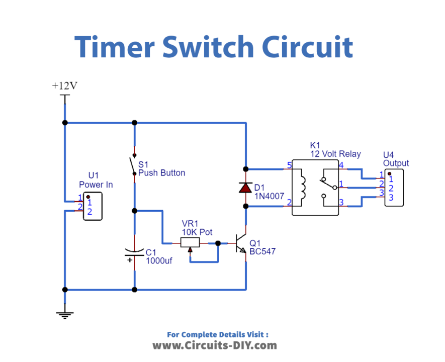
Timer Switch Circuit
Application
- This circuit plays an important role in controlling many process control tasks such as automated control of AC and DC drives, sectionizing and criminalizing factory operations, etc.