Introduction
In electronics, timers are the circuits that provide the signal that changes the state of the system. To understand this, in this tutorial, we are going to “Simple Timer Alarm Circuit using IC 555”. In electronics, timers are the circuits that provide the signal that changes the state of the system. To understand this, in this tutorial, we are going to “Adjustable Timer Circuit using 555”. And, to make this circuit we are using the widely used timer IC NE555.
The 555 timer IC is one of the most used ICs in the electronic circuits world. It’s an integrated circuit that has so many applications in timer, delays, oscillator, and pulse generator. The integrated circuit contains 8 pins having different definitions. The favorable element of this circuit is that it’s reasonable in price and credible like any other op-amp.

Hardware Components
The following components are required to make the Timer Alarm Circuit
| S.no | Component | Value | Qty |
|---|---|---|---|
| 1. | IC | NE555 Timer | 1 |
| 2. | Buzzer | – | 1 |
| 3. | Switch | – | 6 |
| 4. | Electrolyte Capacitor | 470uF | 1 |
| 5. | Ceramic Capacitor | 0.1uF | 1 |
| 6. | Resistor | 100Ω, 20KΩ, 500KΩ, 1MΩ, 2.2MΩ, 1.5MΩ | 1,1,1,1,1,1 |
| 7. | Switch | – | 1 |
| 8. | Battery | 9V | 1 |
NE555 IC Pinout

For a detailed description of pinout, dimension features, and specifications download the datasheet of 555 Timer
Timer Alarm Circuit
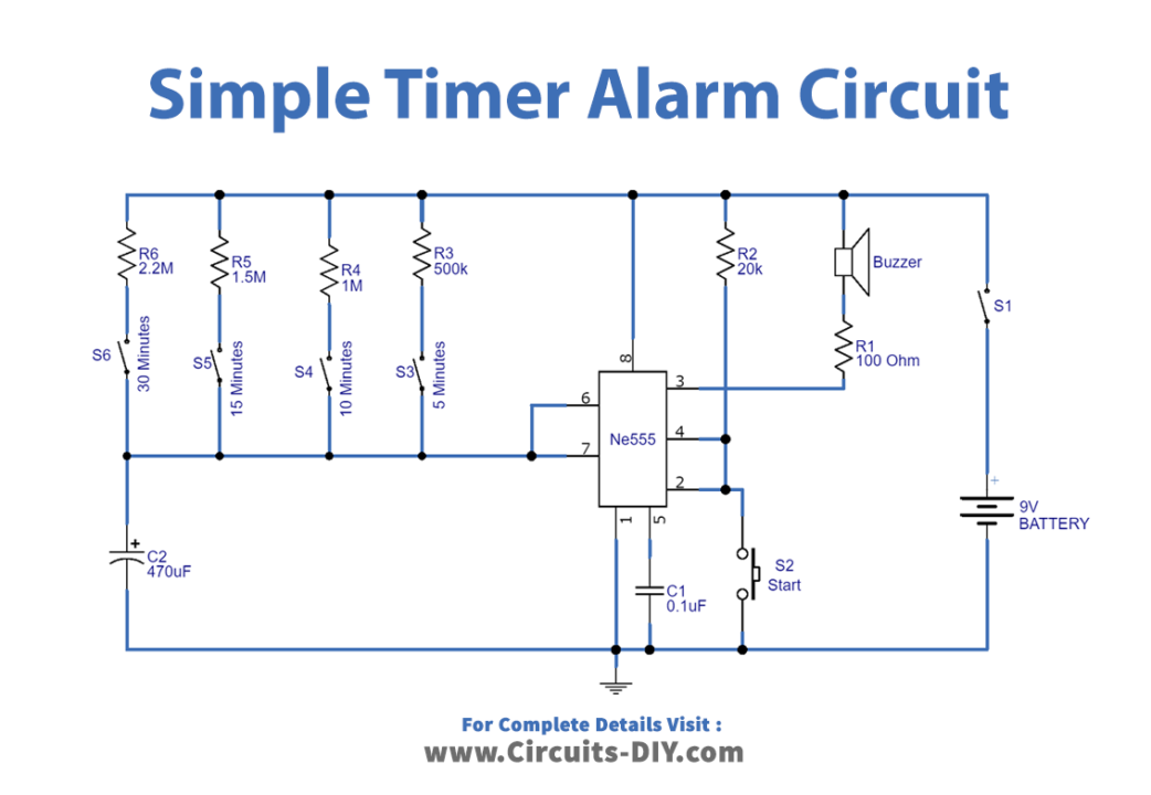
Working Explanation
In this Simple Timer Alarm Circuit, timer IC 555 is the major circuit component with few other components which are easily available, A 9V battery is used as the supply, you can also create your own power supply by using a step-down transformer and Bridge Rectifier circuit. We connected the buzzer at the output pin of the timer IC. The start button is connected at pin 2 and through R2 Resistor. The circuit has a different range of Resistors for various timing ranges. You can turn ON this circuit by closing Switch S1. Choose the timer range by closing the switches S3, S4, S5, or S6 and then press the start switch s2 and then wait. On the output side, the buzzer will give the sound depending on the timing range.
Application and Uses
- Flip-flops.
- Oscillation circuits.
- Pulse width modulation circuits.