
A Flip-Flop LED flashing circuit is a basic circuit that produces a continuous square wave blinking output. This circuit is generally used for indicative & alarming purposes. In this project, we are going to design a simple Flip-Flop LED Flashing Circuit Using an Astable Multivibrator.
An astable multivibrator is a free-running oscillator that switches continuously between its two unstable states. With no external signal applied, the transistors alternately switch from cutoff to saturation state at a frequency that RC time constants of the coupling circuit determine. If these time constants are equal (R and C are equal) then a square wave will generate with a frequency of 1/1.4 RxC. Hence, an astable multivibrator is also a pulse generator or a square wave generator.
Hardware Component
The following components are required to make LED Flashing Circuit
| S.no | Component | Value | Qty |
|---|---|---|---|
| 1. | Breadboard | – | 1 |
| 2. | Battery | 9v | 1 |
| 3. | Connecting Wires | – | 1 |
| 4. | Transistor | BC337 | 3 |
| 5. | LED | 5mm | 2 |
| 6. | Capacitor | 100uF | 2 |
| 7. | Resistor | 12k, 470 ohm | 2,2 |
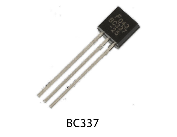
BC337 Pinout

For a detailed description of pinout, dimension features, and specifications download the datasheet of BC337
LED Flashing Circuit

Working Explanation
The heart of this circuit is a BC337 Transistor pair working as an astable multivibrator. The basic principle of an Astable multivibrator is a slight variation in the electrical properties or characteristics of the transistor. This difference causes one transistor to turn on fast than the other when power is switched on for the first time, thereby triggering oscillations. In this circuit, The bias resistors connect directly to the supply and have a value of about 30 times the collector resistor for ordinary gain transistors. The flashing period is approximately the product of this resistance and the capacitance which is about 1 sec. The 470Ω resistors set the LED current and may be reduced for lower battery voltage.
The flashing rate of the circuit can be increased or decreased by changing the values of R2, R3, C1, and C2. The circuit is using two general-purpose BC337 NPN transistors but you can also use other transistors, for example, 2N2222 and 2N4401, etc.
Applications
- Generally used in devices such as toys and doorbells to produce flashing lights or siren effects.
- Also used in devices such as hazard flashers & turn indicators for various automobiles & vehicles.