Introduction
If you have traveled to different countries in the world, You may have noticed that several nations are adopting automated LED street lights that turn on automatically after dusk to conserve energy and power. LDR is used in the circuit of these LED lights. A Light-dependent resistor, or LDR, resists light as the name indicates. As a result, resistance rises as the light intensity rises. The circuit starts operating as it becomes dark, which makes it ideal for street light wiring. So, in this tutorial, we’ll learn how to make an “Automatic Street Light Circuit.” We’re utilizing a 230V bulb for the output. To put it another way, the circuit can easily power a 230V AC device.
This method eliminates the need for physical labor. When the light falls below the ambient light level, it automatically turns on the lights. This is accomplished by the use of LDR, which detects light.
Hardware Components
The following components are required to make an Automatic Street Light Circuit
| S.no | Component | Value | Qty |
|---|---|---|---|
| 1. | LDR | – | 1 |
| 2. | Transistor | BC107, SL100 | 1 |
| 3. | Resistor | 1K | 1 |
| 4. | Relay | 9v | 2 |
| 5. | Fuse | 1A | 1 |
| 6. | Lamp | 230v | 1 |
| 7. | Potentiometer | 100K | 1 |
| 8. | LED | – | 1 |
| 9. | White LED Array | – | 1 |
| 10. | Switch | – | 1 |
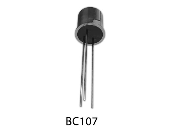
BC107 Pinout

For a detailed description of pinout, dimension features, and specifications download the datasheet of BC107
SL100 Pinout
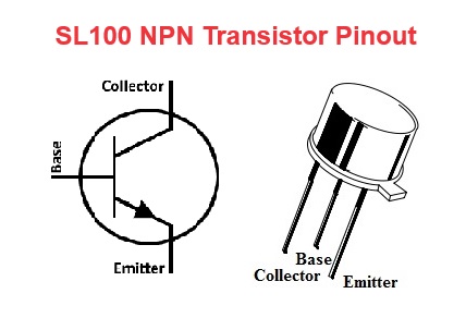
For a detailed description of pinout, dimension features, and specifications download the datasheet of SL100
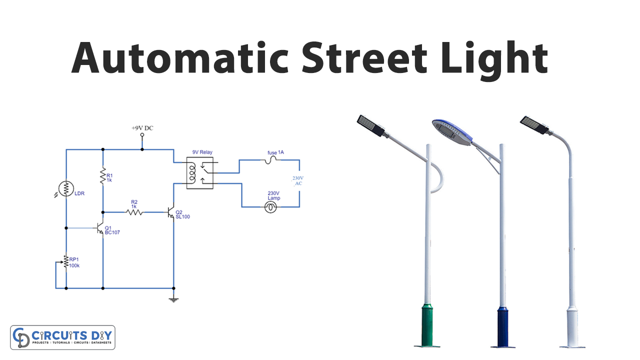
Automatic Street Light Circuit
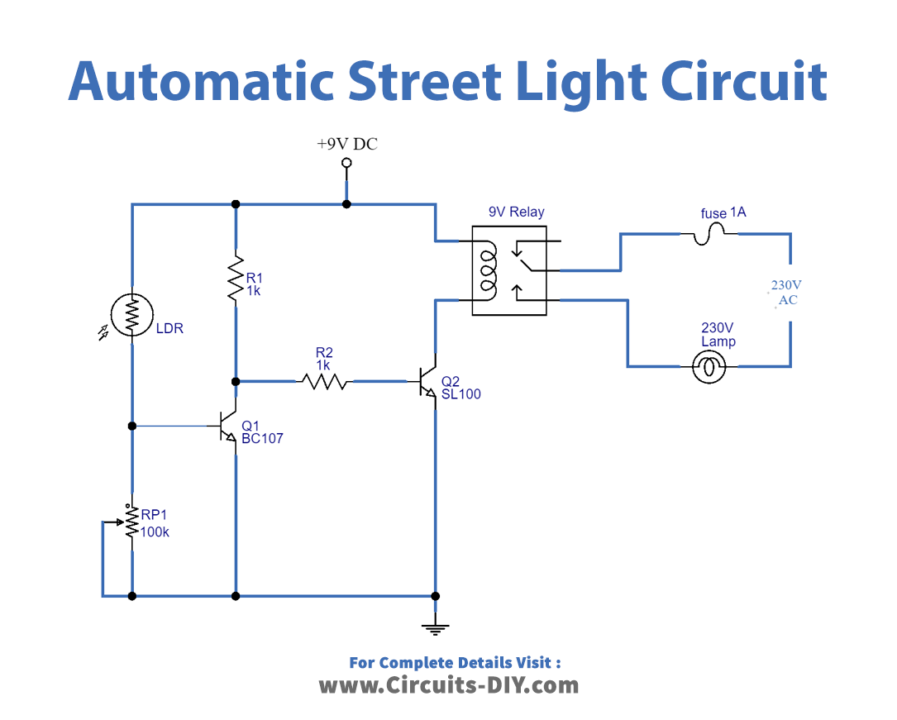
Working Explanation
In this Automatic street light circuit, we are using LDR, when light falls on the LDR in this Automatic Street Light Controller, it becomes a less resistive element, allowing bias to form at the transistor Q1 base. It activates transistor Q1. Because transistor Q2 has no bias at its base, it remains turned off. The Relay coil does not receive power in this situation, therefore it remains turned off.
When no light falls on LDR, it transforms into a highly resistant element. In this situation, there is no bias at the base of the Q1 transistor, therefore Q1 is turned off, and when bias is applied to the base of the transistor, Q2 is turned on. The Relay coil now has electricity and is consequently activated. So, the output bulb glows.
Application and Uses
- When the power goes off, the Light Circuit automatically turns on the lights. And, therefore, used as street lights.