Introduction
Do you ever find yourself frustrated with weak radio signals and poor reception while trying to tune into your favorites station? The solution to your problem could be just a few circuits away. Introducing the VHF preamp circuit – the unsung hero of radio reception. This simple circuit can boost those weak signals, providing a crystal clear sound experience.
Whether you’re a seasoned electronics enthusiast or a beginner looking to improve your skills, this guide will walk you through the process of building a VHF preamp circuit from scratch. Get ready to say goodbye to fuzzy audio and hello to a world of clear and concise sound.
Hardware Required
You will require the following hardware for VHF Preamp Circuit.
| S.no | Components | Value | QTY |
|---|---|---|---|
| 1 | Capacitor | 1nF | 4 |
| 2 | Variable Capacitor | 18p | 2 |
| 3 | Resistor | 22k, 47k, 100 | 1, 1, 2 |
| 4 | Inductor | – | 1 |
| 5 | Transistor MOSFET | – | 1 |
Circuit Diagram

Working Explanation
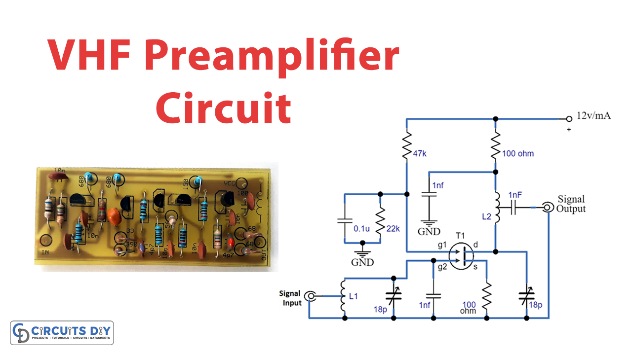
The circuit consists of two air-cored coils, L1 and L2, which are wound using 4 turns of 1mm silver-plated copper wire with an internal diameter of 6mm. L1 is one turn away from the earthy end, while L2 has a tap one turn away from the end closest to R3. The four 1n capacitors used in the circuit are typically ceramic types.
With a bandwidth of 2 MHz and noise figure of 2.5 dB, this circuit offers a remarkable dynamic range and a gain of 20 dB at 144 MHz. The circuit is easy to work with and is quite affordable, making it accessible to both hobbyists and professionals alike.
Final Words
The VHF preamp circuit is versatile and effective, well-suited for various applications. The circuit is easy to construct, affordable, and easily integrated into other systems. With its impressive dynamic range and gain, it is an excellent choice for anyone looking to improve the performance of its VHF system.