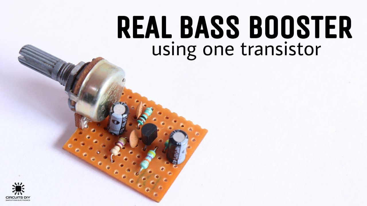
Sound quality is an important factor for any live production or entertainment media, whether it be a small recording session or a full-out live EDM concert. With the new trends in the entertainment industry, it has become ever so necessary to have the very best equipment available to ensure the utmost performance, especially in terms of sound quality. So, in this project, we are going to go over a step-by-step procedure on How to Make A Simple Bass Booster using a single transistor and a small number of other components.
JLCPCB is the foremost PCB prototype & manufacturing company in china, providing us with the best service we have ever experienced regarding (Quality, Price Service & Time).
What is a Bass Booster?
An Electronic Bass booster is an electronic circuit that operates in conjunction with an amplifier circuit, improving its output response. It is commonly fitted in basic consumer electronics such as speakers, gaming headsets & earbuds to improve the listening experience.
Hardware Components
The following components are required to make Bass Booster Pre Amplifier Project
| S. no | Component | Value | Qty |
|---|---|---|---|
| 1. | Transistor | 2n2222 | 1 |
| 2. | Audio Jack with cables | 3.5mm, Male/Female | 2 |
| 3. | Capacitors | 47uF, 100nF, 100uF | 4 |
| 4. | Potentiometer | 100K | 1 |
| 5. | Speaker | 8 Ohm | 1 |
| 6. | Resistor | 470K, 47K, 10K, 470 Ohm | 1 |
| 7. | Soldering Iron | 45W – 65W | 1 |
| 8. | Soldering Wire with Flux | – | 1 |
| 9. | DC Battery | 9V | 1 |
| 10. | Battery Clip | – | 1 |
| 11. | Veroboard | – | 1 |
| 12. | Jumper Wires | – | As per need |
2N2222 Pinout
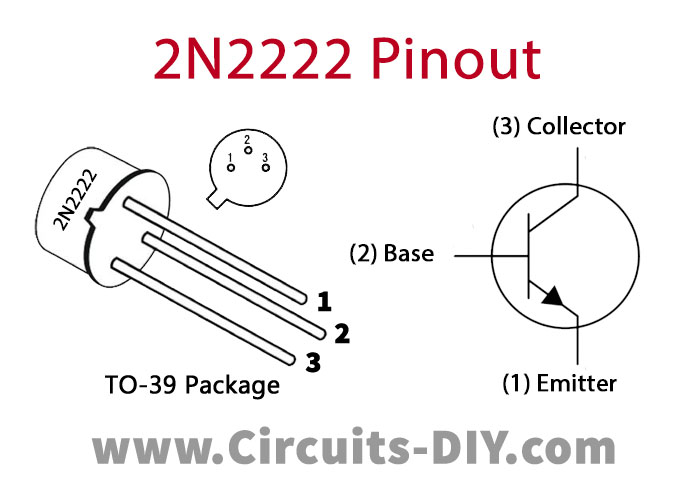
For a detailed description of pinout, dimension features, and specifications download the datasheet of 2N2222
Useful Steps
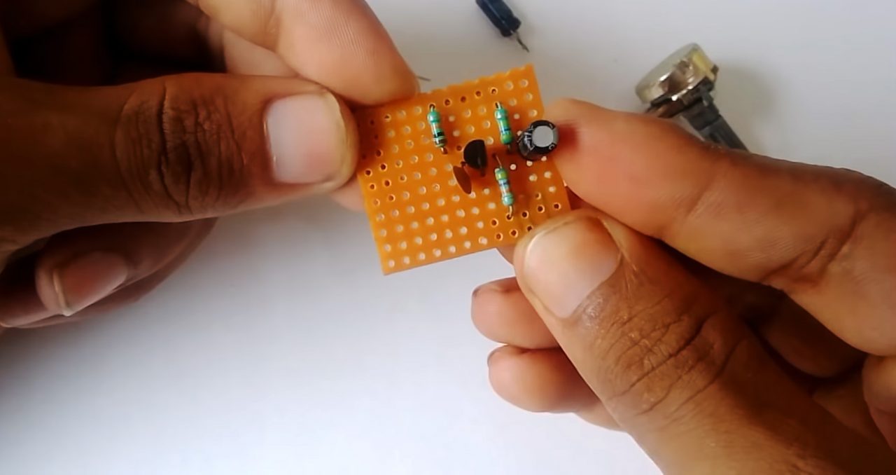
1) Solder the 2n2222 transistor on the Veroboard, after that solder a 47K resistor between the base of the transistor & the ground of the circuit.

2) Solder a 470K resistor from the base of the transistor to Vcc of the circuit. After that, solder the +ve terminal of a 47uF capacitor to the base of the transistor (Audio IN).

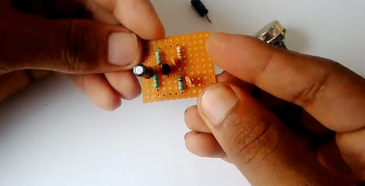
3) Connect a 100pF capacitor between the emitter & base pin of the transistor. Then, connect a 10K resistance between the collector pin of the transistor & Vcc of the circuit.
4) Connect a 470 Ohm resistance between the collector of the transistor & the Vcc of the circuit. After that, connect a 100pF capacitor between the collector of the transistor & the Vcc of the circuit.
5) Connect a 47uF capacitor between the collector terminal of the transistor & the Audio OUT of the circuit. Also, Solder a 100K pot to the Audio OUT.
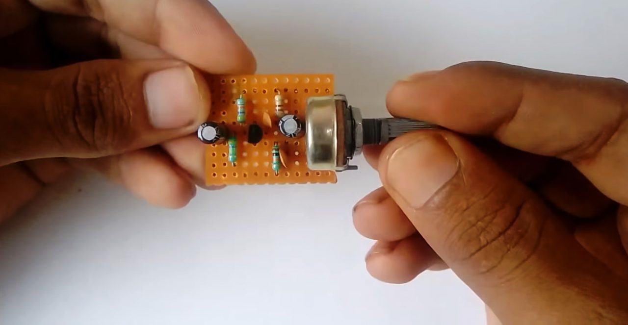
6) Connect the 9V battery clip. Solder the speaker input between the middle terminal of the 10K pot & the GND of the circuit.

7) Connect the Audio IN between the 47uF capacitor & GND of the circuit.
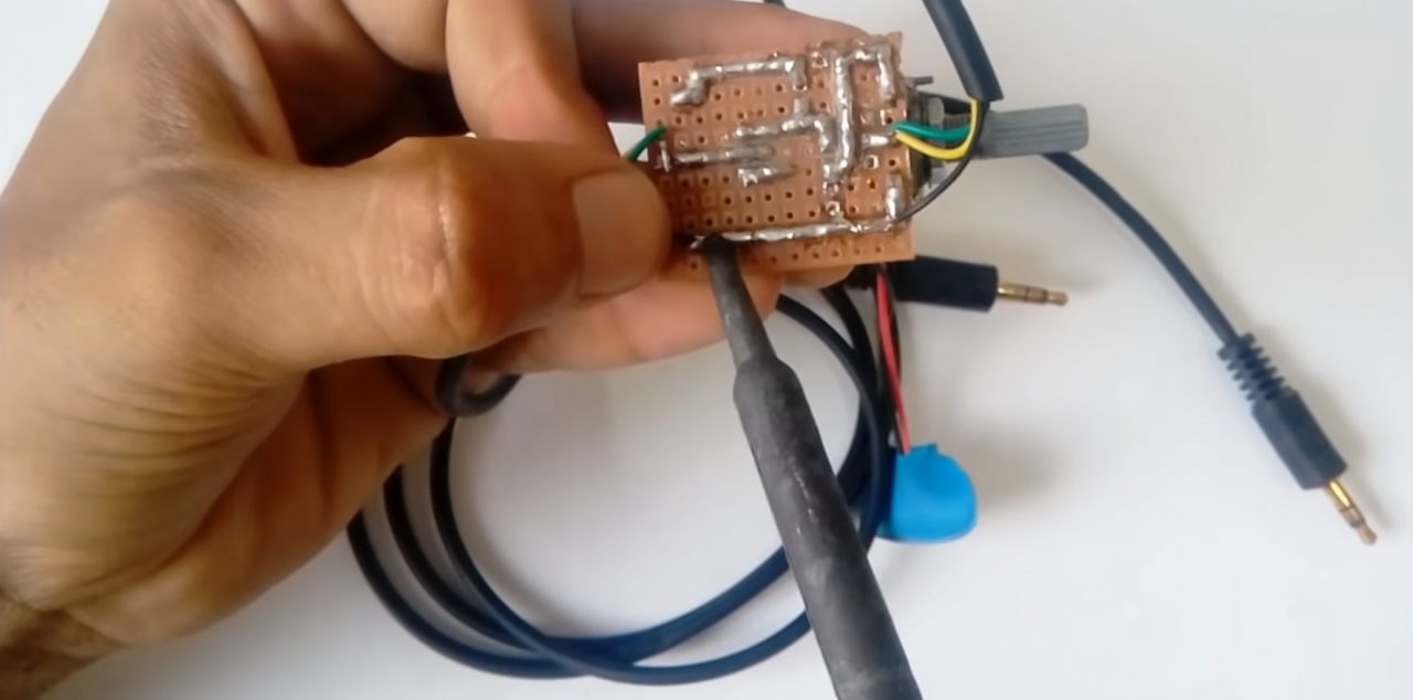
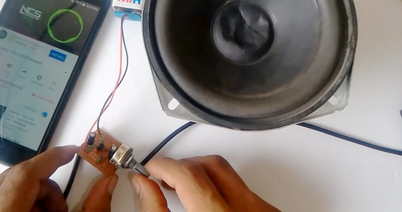
8) Solder the Audio OUT to an 8 Ohm speaker. Power up & test the circuit.
Working Explanation
Audio input is taken from a device such as a microphone/smartphone. The input goes to the base of the 2n2222 transistor acting as a control signal. Here, a 100uF capacitor is connected to the base of the transistor, blocking the DC component while allowing the AC component of the signal to pass through.
The amplified collector output passes through a filter capacitor (47uF) to remove any residual noise from the output. The amplitude of the output audio signal can be adjusted by a preset pot (100K) before being sent to the 8 Ohm speaker.
Applications
- Mostly used in speakers & home entertainment systems.