Introduction
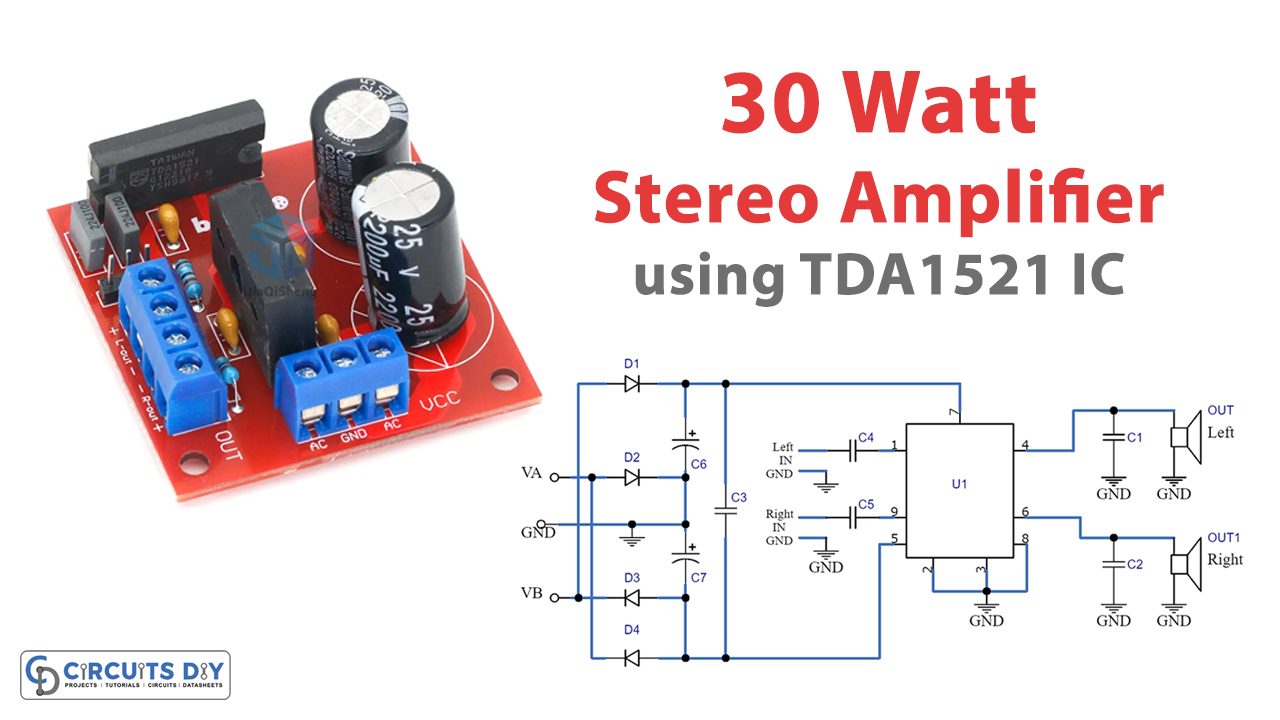
This article explains how to build a 30-watt stereo amplifier circuit using a single IC, the TDA1521. This circuit is simple to build and troubleshoot, making it a popular choice for audio enthusiasts. The circuit includes the TDA1521 IC as its major component.
The TDA1521 is a Philips monolithic integrated circuit with an ultimate dual BF capable of delivering 10 to 12 W to an 8-ohm or 15 W on a 4-ohm speaker. The amplifier has a gain of 30 dB, around 32 times. To understand that more, let’s dig this article further.
Hardware Required
You will require the following hardware for Stereo Amplifier Circuit.
| S.no | Components | Value | QTY |
|---|---|---|---|
| 1 | IC | TDA1521 | 1 |
| 2 | Polar capacitor | – | 2 |
| 3 | Non polar capacitor | – | 5 |
| 4 | Resistor | 20k, 680k | 1, 1 |
| 5 | Diode | – | 4 |
| 6 | Speaker | 4 | 2 |
Circuit Diagram

Working Explanation
The circuit diagram shows the simplicity of this integrated circuit for creating a hi-fi amplifier. The diagram only shows one of the two channels, as the second channel is identical. The settings are optimized for the application of the signal to the non-inverting input (-INV) based on the ground.
The dual power supply allows the inverting inputs (INV1 and INV2, respectively, pins 2 and 8) and reference point (pin 3) to be grounded. The feedback system is a parallel/series. It requires a portion of the output voltage and feeds it back to the inverting input of the first operational amplifier through a bridge of 20 k and 680 k resistors.
The input signal of the circuit extends to pin 1 via C4, is amplified for the first time, and then sent to the input of a second stage, which boosts the level and reverses its phase before delivering it to the power segment produced in balance by two built-in transistors, an NPN and a PNP. These BJTs run in an emitter-follower, amplifying only the current and leaving the phase signal unchanged at the circuit’s input.
Protection Features:
The TDA1521 also includes several protection features, such as a delay network that switches off the input stage during power-up to prevent amplifying low frequencies before the power supply has stabilized. A voltage window comparator consisting of two op amps monitors the power supply. In operation, the two 10 k resistors determine a 0 V potential at the line ending at pin 3, i.e. the ground potential.
However, asymmetries may occur during power-up, causing the potential on the positive line to differ significantly from that on the negative line. This could result in a distorted signal, so the comparator intervenes, setting the outputs of the two op-amps at a low level (0 V) and deactivating the first op-amps to balance the amplifiers. When the power is stabilized, the comparator updates its output level too high. It regulates the power to the input stage, allowing the music signal to be amplified and delivered to the speakers.
The TDA1521 also provides short circuit protection on the output terminals (on one or both channels) for one hour. Overheat protection is also provided by monitoring the temperature of the IC and shutting down the circuit if necessary.
Final Words
Using the TDA1521, the 30-watt stereo amplifier circuit is a small and effective way to boost audio signals. The circuit is easy to build and troubleshoot, making it an excellent option for beginners. The TDA1521’s built-in protections and voltage window comparator ensure that the amplifier operates smoothly and reliably.