In this tutorial, we are going to make a “4 transistor audio amplifier circuit”. The amplifier is simple to construct and is adaptable to your individual requirements. This transistor audio amplifier circuit might be ideal if you want to build your own amplifier or upgrade an existing one. Even those with little prior knowledge of electronics can easily construct this audio amplifier circuit. The compact size of the circuit makes it a fantastic option for applications where available space is at a premium. The circuit contains a complementary push-pull amplifier with four transistors that demonstrates the fundamentals of audio amplifier design. With a medium volume, the battery current used by this circuit is quite low.
Hardware Required
| S.no | Component | Value | QTy |
|---|---|---|---|
| 1. | Resistor | 1K, 33K, 56K, 10K, 100K, 270 Ohm, 470 Ohm | 1, 1, 1, 1, 1, 1, 1 |
| 2. | Capacitor | 10uF, 1uF, 100uF | 1,1,1 |
| 3. | Speaker | – | 1 |
| 4. | NPN Transistor | BC547 | 2 |
| 5. | PNP Transistor | BC557 | 2 |
| 6. | Switch | – | 1 |
| 7. | Battery | – | 1 |
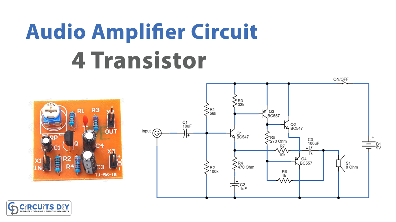
Circuit Diagram
Working Explanation
In this 4 Transistor Audio Amplifier Circuit, both transistors Q3 and Q4 are configured as a complementary pair that operates in push-pull mode. Each output transistor handles one-half of the audio cycle, with one turned off while the other conducts. The Q1 and Q2 transistors then function as a pre-amp to boost the arriving voltage to drive the output pair.
The bias of the entire circuit then begins at Q1 with the voltage divider comprised of the 56K and 100K resistors. This provides a bias voltage of 5.5V to the base. The emitter voltage will be 4.9V, which is 0.6V less than this. The Q2-transistor is then biased to provide a voltage now across a 270-ohm load resistor, resulting in the output transistors
Application Uses
- In a variety of settings, such as homes, offices, and vehicles, the transistor audio amplifier circuit could be used to amplify audio signals.
- It is portable and application-friendly due to its efficiency and compact design.