Introduction:
An oscillator is an electronic device that produces periodic, replicated, oscillating waveforms without the supply of input. It may be a sine wave, triangular or square wave. It converts the one-directional DC source into an alternating signal.
Oscillators are mainly classified into relaxation/non-linear oscillators or harmonic oscillators based on their working principle.
A relaxation oscillator exchanges the energy between active and passive components and the charging and discharging time-constant determine its frequency. While harmonic oscillators are those in which the flow of energy is from active to passive components and its frequency is determined by the feedback path.
This post discusses the working explanation of the Colpitts oscillator circuit and its applications. The Colpitts oscillator circuit is a type of LC circuit that is a combination of inductor and capacitor that produce an oscillation at a defined frequency.
Hardware Components
The following components are required to make Colpitts Oscillator Circuit
| S.no | Component | Value | Qty |
|---|---|---|---|
| 1. | Transistor | BC547 | 1 |
| 2. | Inductor | 10mH | 1 |
| 3. | Resistor | 100KΩ, 5KΩ, 1KΩ, 10KΩ | 1 |
| 4. | Capacitor | 0.01μF, 100pF, 100nF | 2, 2, 1 |
| 5. | Battery | 9V | 1 |
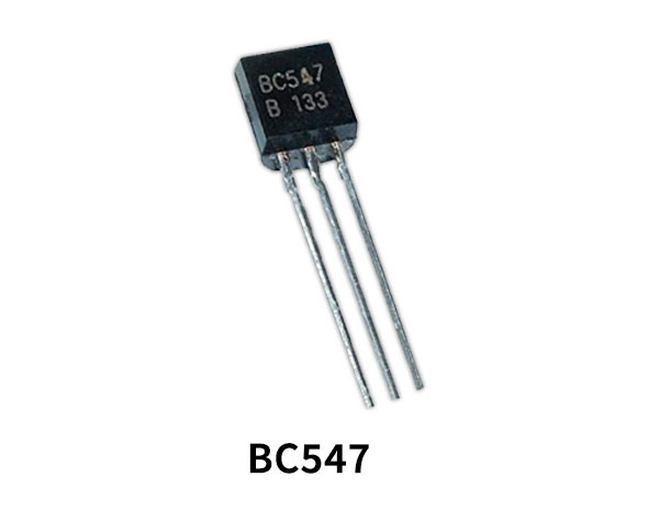
BC547 Pinout

For a detailed description of pinout, dimension features, and specifications download the datasheet of BC547
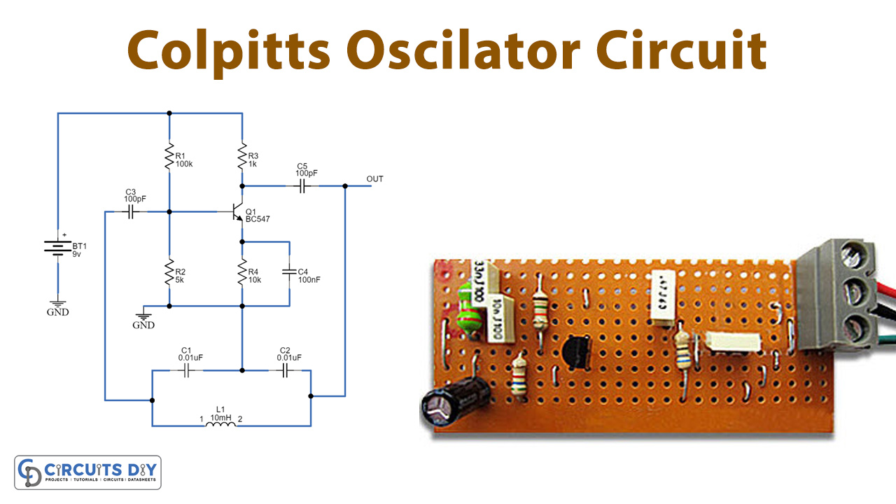
Colpitts Oscillator Circuit

Working Explanation
The Colpitts oscillator circuit contains only a few components arranged in the following order. The inductor is connected in parallel to the series capacitors C1 and C2 (tapped capacitors). The transistor BC547 works as an emitter follower where R1 and R2 resistors bias the CB (collector-base) terminals and BE (base-emitter) terminals while the collector and base terminals have a tank circuit in their feedback path.
When the power supply is provided to the circuit, both the capacitors C1 and C2 get charged and then discharge through the inductor which initially produces oscillations. These oscillations at C2 are applied to the transistor base-emitter terminal which amplifies it and is obtained at the collector terminal. The amplified signal is supplied to the tank circuit to meet out losses during the conversion of energy between the two capacitors and inductors. The values of two capacitors C1 and C2 decide the feedback amount. The total phase shift of 360º is obtained, the transistor provides a 180º phase shift while the capacitor feedback provides another 180º phase shift, and hence total 360º phase shift is obtained which provides a positive feedback value. In the end steady, smothered oscillations are obtained.
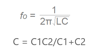
Colpitts oscillator circuit formula:
Applications:
The Colpitts oscillator is applicable to many applications. Some are as follows:
- It can be used as a radio frequency oscillator.
- It is used in communication systems and mobile phones or tablets.
- It is applicable in high-frequency sine wave generators.
- Furthermore, it is applicable for many other commercial purposes.
Advantages:
The Colpitts oscillator has the following advantages:
- It is not affected by high or low-temperature variations.
- The circuit requires few components to operate.
- It has high-frequency stability, and it generates a high-frequency sine wave.
- Both the variable capacitors are used to vary the frequency.
- The amplitude of the output does not change over a fixed range of frequency.
- Hence, the Colpitts oscillator generally does not have any particular disadvantage.