Introduction
Amplifiers are devices that increase the system’s input power at the output. Audio amplifiers boost the amplitude of audio input signals. The gain of the circuit helps explain the amplification of the circuit’s output. As a result, every amplifier’s power gain exceeds one. We typically find amplifiers in electrical equipment or devices. Pre-amplifiers and power amplifiers are two types of amplifiers. There are several types of power amplifiers. The audio amplifier is a type of power amplifier. So, in this tutorial, we are going to make a “5V USB Audio Amplifier Circuit Diagram”. We’ll create this audio amplifier with an integrated circuit called the NS8002.
The NS8002 Amplifier IC handles a broad range of voltages from 2.20 to 5.5volts and is best suited for USB-powered applications. This IC is an audio power amplifier that is bridged. Maximum driving power at 5V operating voltage is 3W. The device application circuit is simple, with only a few peripheral components.
Features of NS8002
- High output power (THD + N <10%): 3W (3Ω load)
- Power-down mode leakage current: 0.6μA (typical)
- 3High ShutDown
- Externally adjustable gain
- Wide operating voltage range 2.2V ~ 5.5V
- Without drive output coupling capacitors, bootstrap capacitors and snubber networks
- Using SOP package.

Hardware Required
| S.no | Component | Value | Qty |
|---|---|---|---|
| 1. | IC | NS8002 | 1 |
| 2. | Speaker | – | 1 |
| 3. | Switch | – | 1 |
| 4. | Capacitor | 0.1uF, 1uF | 1, 2 |
| 5. | Resistor | 10KΩ, 100KΩ, 47KΩ | 1, 1, 1 |
| 6. | 2-Pin Connector | – | 1 |
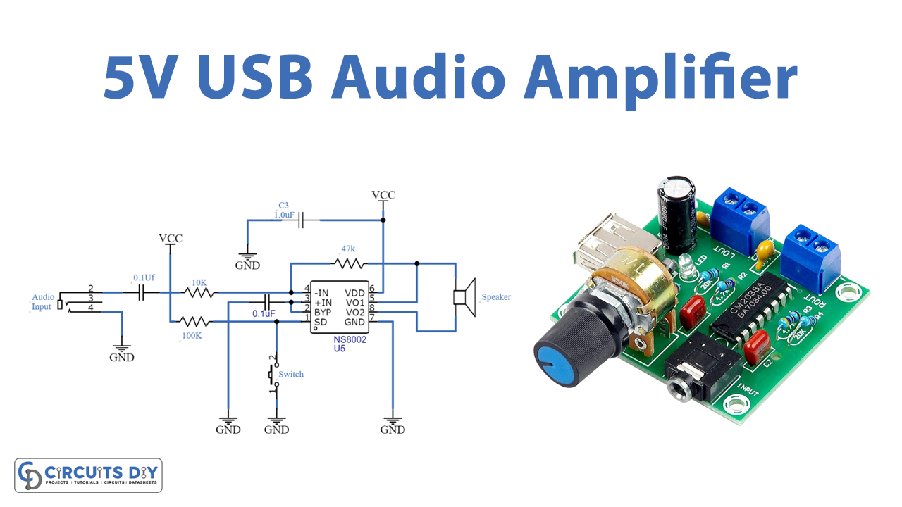
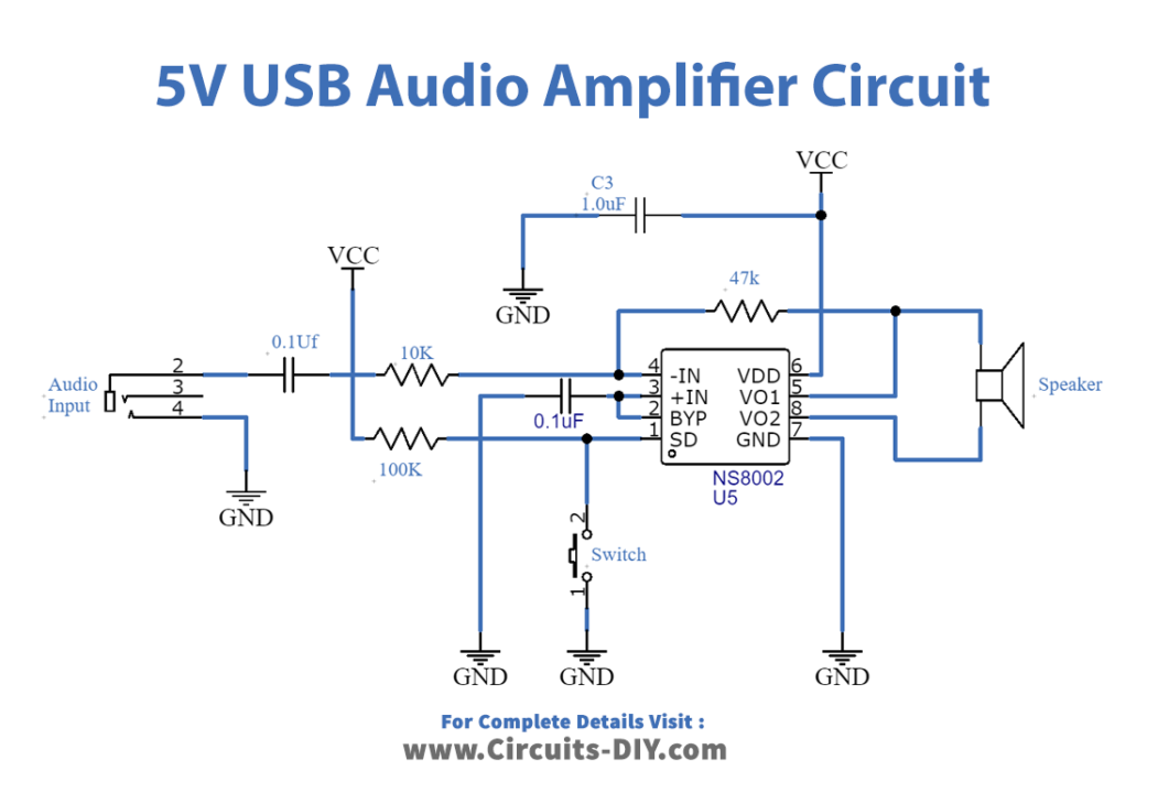
Circuit Diagram
Working Explanation
- When a high level is provided to pin 1 of the IC NS8002, the amplifier enters shutdown mode.
- There is a switch connected between pin 1 and ground that symbolizes low level; if the switch is open, a high level is applied.
- I knew pin 2 as BYP or Bypass Capacitor Pin, and it is responsible for providing the common-mode voltage.
- first amplifier’s positive input pinn3 and gets the common-mode voltage through the C2 capacitor.
- Pin 4 is a -IN connector. The audio input signal is received by the first amplifier’s negative input through coupling capacitor C1 and resistor R1.
- Vo1 (pin 5) provides a negative output for a loudspeaker.
- Pin 6 is Vcc and connects to the Analog Vcc input supply (+5V), whereas pin 7 is GND and connects to the circuit ground.
- Vo2 (pin 8) provides a positive output for a loudspeaker. R3 serves as a feedback resistor between the input and output.
Application and Uses
- it’s great to utilize in public address systems.
- It’s also found in stereo systems.
- Furthermore, it has the potential to be used in guitars and electronic keyboards.
- Theatrical systems also used this circuit.
- Televisions, laptops.
- Headphone drivers, etc.