Introduction
Amplifiers are considered one of the fundamental electronic circuits. The industry is full of tons of amplification designs and circuits. Designers try their best to make quality amplification designs that can be used in so many applications. Hence there is a bunch of amplification integrated circuits available in the market that can be utilized in various devices. One of the in HT82V739. So, in this tutorial, we are going to “1200 mW audio amplifier circuit”
HT82V739 Features
- Operating voltage: 2.2V to 5.5V
- High signal-to-noise ratio
- Low distortion
- Large output voltage swing
- Low power consumption
- Output power 1200mW at 10% THD+N into 8
- (VDD=5V)
- Wide temperature operating range
- Low power-on and chip enable or disable POP noise.
- Low standby current
- Power off control
- Direct drive speaker
- 8-pin SOP package
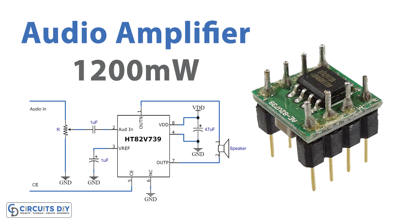
HT82V739 Pinouts


Hardware Required
| S.no | Component | Value | Qty |
|---|---|---|---|
| 1. | IC | HT82V739 | 1 |
| 2. | Speaker | 8 ohms | 1 |
| 3. | Capacitor | 1uF, 47uF | 2, 1 |
| 4. | Potentiometer | R | 1 |
| 5. | 2 Pin Connector | – | 2 |
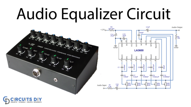
Circuit Diagram
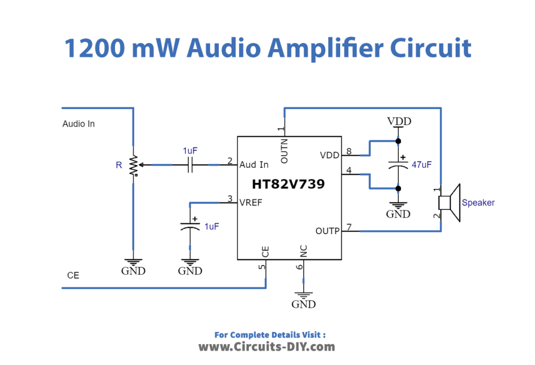
Working Explanation
This 1200 mW audio amplifier circuit requires very few external components because this HT82V739 IC which is working as the major component does most of the work. To adjust the volume we have wired the potentiometer of 20k at the input side. We connected the speaker at the output pins while capacitor C2 is there for filtration purposes. when you connect the supply and give input audio to the circuit, it provides the amplified output at the load. Thus you need to adjust the potentiometer to get a good sound from the speaker.
Application and Uses
- Hi-fi devices.
- Children’s toys.
- Robotic applications
- Television and computers, etc.