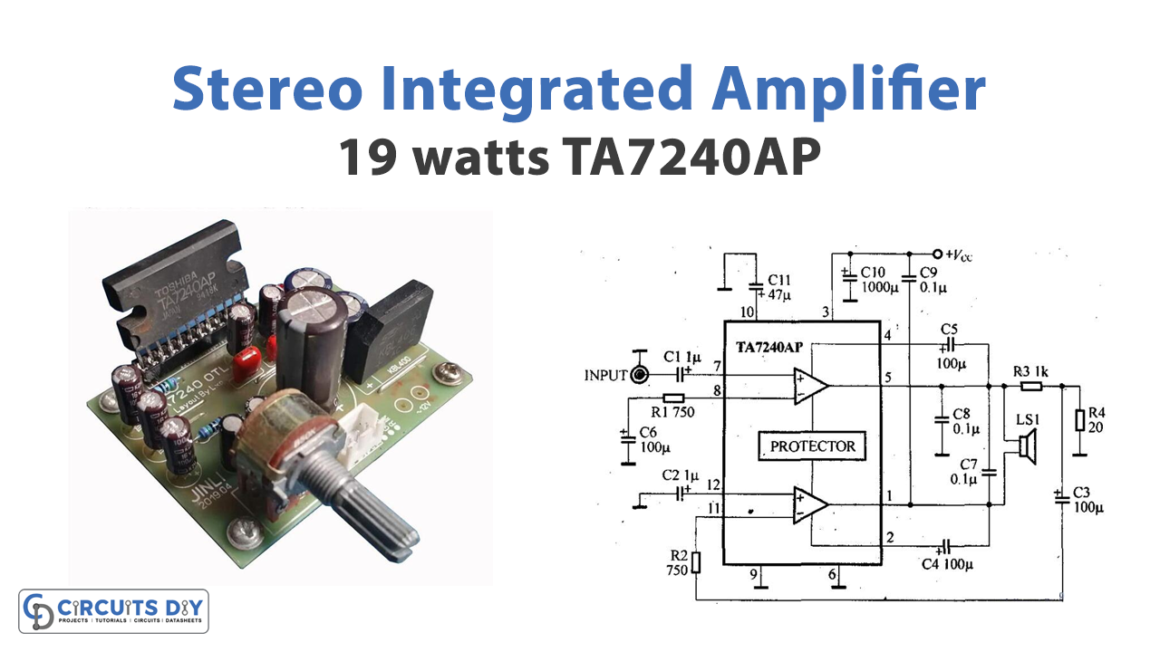
In this Tutorial, we are going to make a “TA7240AP 19-Watts Stereo Integrated Amplifier”. The TDA7240A is a bridge audio amplifier integrated circuit. The IC has several useful functions such as loudspeaker protection, short circuit protection, low noise, thermal shutdown, low distortion, low noise, high current capability, and so on.
Features
- Wide supply voltage range: 9V to 18V.
- Supply current: 1.5 Amp
- Total Harmonic Distortion Noise(THD): 1% at 15 watts and 10% at 19 watts
- Noise signal: lower than 0.14 mV
- Boost up the rate of tone control: + 20dB
Hardware Required
| S.no | Component | Value | Qty |
|---|---|---|---|
| 1. | IC | TA7240AP | 2 |
| 2. | Op-amp IC | TL072 | 1 |
| 3. | Resistor | 4.7K, 8.2K, 47K, 56K, 39K, 10K, 1K, 20 ohm, 220 ohm, 750 ohm | 1, 4, 1, 1, 1, 1, 1, 1, 1, 2 |
| 4. | Electrolytic Capacitor | 1uF, 10uF, 22uF, 100uF, 1000uF, 2,200uF | 2, 1, 2, 5, 1, 1 |
| 5. | Ceramic Capacitor | 560pF, 0.0033uF/50V, 0.1uF/50V, 0.05uF/50V | 1, 2, 4, 3 |
| 4. | Toggle Switch | 6 lead | 1 |
| 5. | Variable Resistors | 100K | 4 |
| 6. | Diode | 1N5401 | 1 |
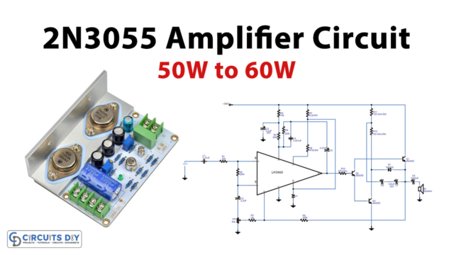
Circuit Diagram

Working Explanation
This TA7240AP circuit operation is divided into two parts:
- The tone control circuit having IC1
- The power amplifier utilizing IC2
Tone Control Circuit
A signal enters the tone control circuit by potentiometer VR1, which allows you to adjust the sound level as necessary. A loudness circuit that boosts sound volume at both high and low frequencies is made up of the capacitors C1, C2, switch SW1, and resistor R1. If potentiometer VR1 is turned up to roughly halfway when the volume is on low, the loudness circuit will not function. The volume button is used when a signal passes through VR1 and VR2 and has to be modified to balance the sound between the left and right channels.
The tone control circuit will be fed the opposite way to alter the bass-treble sound level, with VR3 being set as the bass button and VR4 being set as the treble button. When the circuit’s boost cut rate is around +20 dB, the signal is input to pin 2 through IC1 and amplified to pin 1. R5 and C7 will receive a portion of the signal to adjust the bass-treble sound intensity.
When using the op-amp on pin 3 of IC1 with positive and negative voltage, the resistors R6, R7, and capacitor C8 serve as a reference voltage. As the coupling signal into the power amplifier sector, the signal is modified from IC1’s output pin 1 through C11. To regulate the signal’s amplitude from the tone control sector for suitable feeding to the power amplifier sector, R8 and R9 are inserted into C12.
Power Amplifier Circuit
The amplifier component of IC2 internally contains two amplifiers. Each pair will have an output power of 5.8 watts per channel, but when we bridge them together, the power increases to 19 watts per channel. Since we established this 180-degree phase difference in both amplifiers, the output goes directly to the speaker. So, the speaker receives the amplified signal
Application Uses
- Streamers
- CD players, etc