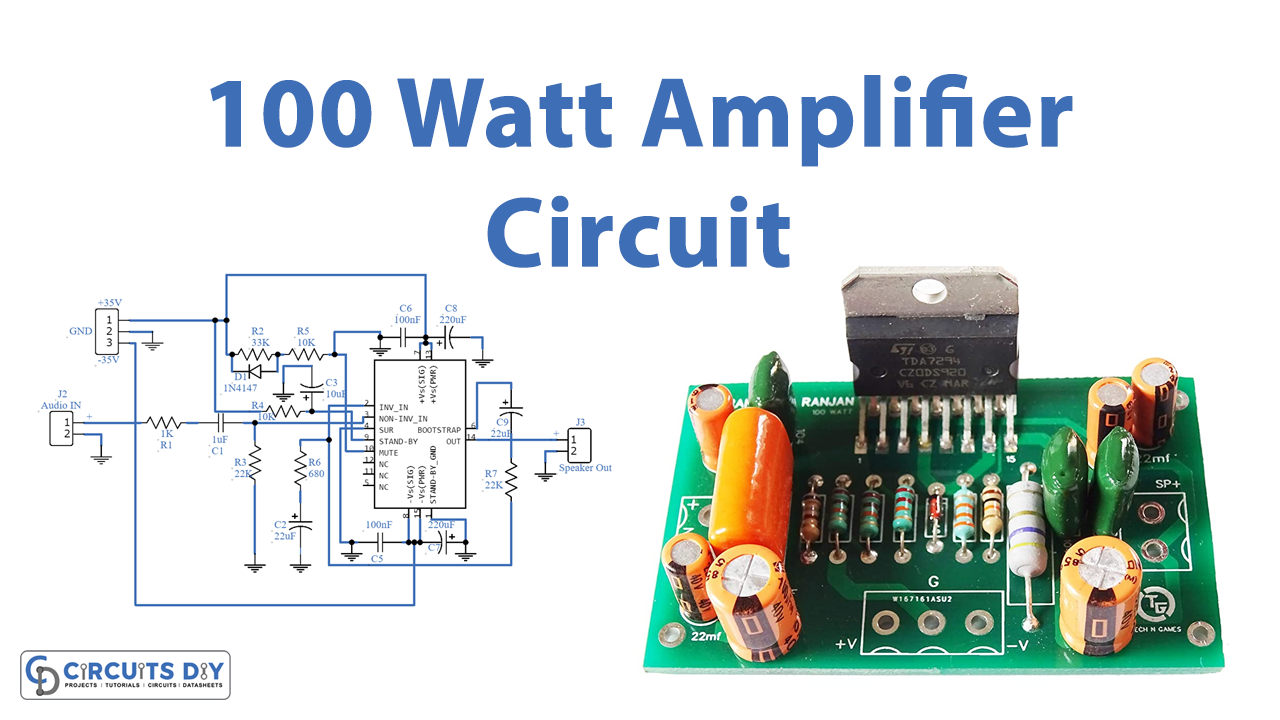
Introduction
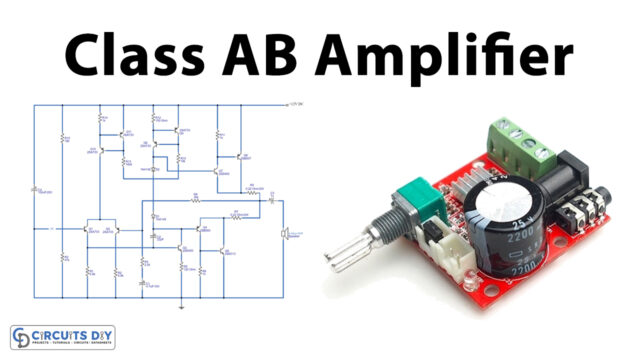
In our tutorials and articles, we have widely discussed many types of amplifier circuits. Here we are again with another audio amplifier circuit for the loud output audio. As we already know that basic operation of an audio amplifier is to boost up the weak input audio signal at the output side. A microphone circuit is maybe the easiest example to understand audio amplifiers. But for the good loud audio at the load side, they have come up with a “100 Watt Amplifier Circuit”. Thus, to make this circuit, we are using TDA7294V IC. This amplifier IC belongs to the class AB amplifiers and is mostly used in the Hi-Fi application. Moreover, the Ic also includes the mute and the standby operations. Therefore, is a prominent option for audio amplifier circuits.
Hardware Required
| S.no | Component | Value | Qty |
|---|---|---|---|
| 1. | IC | TDA7294V | 1 |
| 2. | Diode | 1N4148 | 1 |
| 3. | Electrolysis Capacitor | 10µF, 22uF, 220uF | 2, 2, 2 |
| 3. | Ceramic Capacitor | 1µF, 100nF | 1, 2 |
| 4. | Resistor | 1K, 10K, 22K, 33K, 680Ω | 1, 2, 2, 1, 1 |
| 5. | 2-Pin, 3-Pin Connector | – | 2,1 |
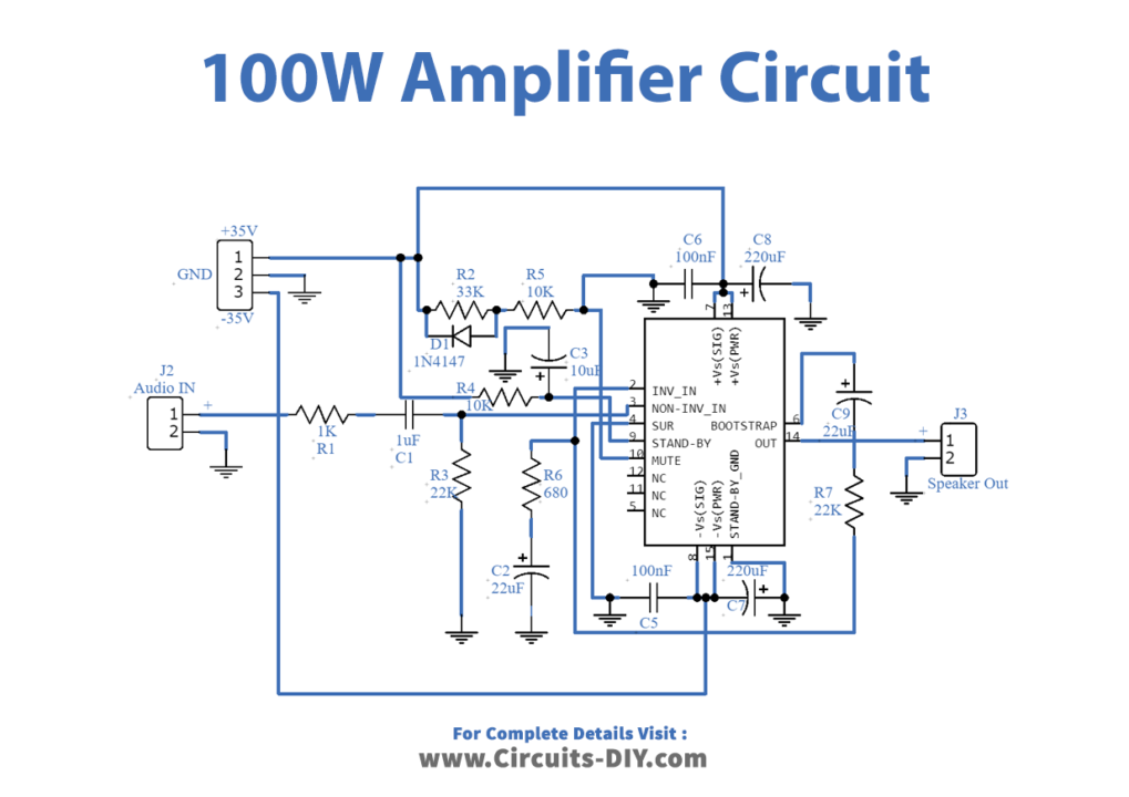
Circuit Diagram
Working Explanation
This 100 Watt Amplifier Circuit uses the monolithic class AB amplifier IC. There are two input pins. Pin 2 for the inverting input, while pinning 3 for the non-inverting input. The audio signal is provided at pin 3 of an IC. Pin 9 and 10 are for the standby and mute options respectively. Pin 13 and 15 are for the positive and negative power supply terminals respectively. The output load is connected at pin 14. After these connections, the IC performs the amplifying operations and provides the low noise and low distortion amplified audio signal to the speaker.
Application and Uses
- Firstly, it can be Self-powered loudspeakers.
- Also, can be utilized for the radio.
- In the home stereo systems.
- For the television speakers.