
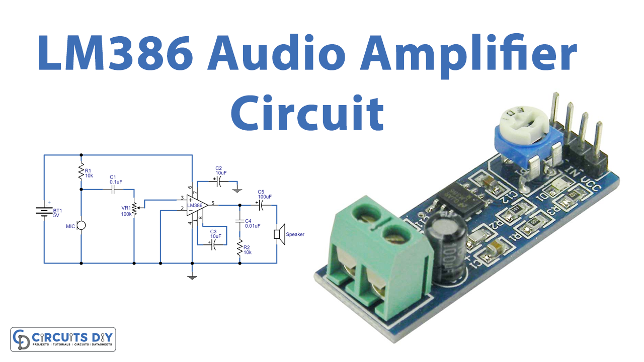
Introduction
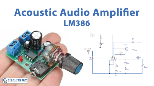
The amplifier circuit can be made in different ways with different configurations or by different components. Widely, designers used transistors to make these amplifiers but with time when electronics evolved more, integrated circuits make the work easier and simple. Now, different ICs can be used to build the amplifiers. In this tutorial, we are making the LM386 Audio Amplifier Circuit.
There are some pros and features of this IC. This IC allows the supply voltage of 3 to 15V. And, can allow a maximum analog voltage of 0.4V. The LM386 IC has a voltage gain of 26db to 46db. Also, the speaker impedance is 4 ohms. The IC comes with 8 pins. So, before making the circuit let’s understand the pin configuration.
Hardware Required
| S.no | Component | Value | Qty |
|---|---|---|---|
| 1. | Audio Amplifier IC | LM386 | 1 |
| 2. | Condenser Mic | – | 1 |
| 3. | Potentiometer | 100KΩ | 1 |
| 4. | Speaker | 8Ω | 1 |
| 5. | Ceramic Capacitor | 0.1μF, 0.01μF | 1, 1 |
| 6. | Electrolytic Capacitor | 10μF, 16V, 100μF, 16 | 2, 1 |
| 7. | Resistor | 10KΩ | 2 |
| 8. | Battery | 5V | 1 |
| 9. | 2-Pin Connector | – | 2 |
Circuit Diagram
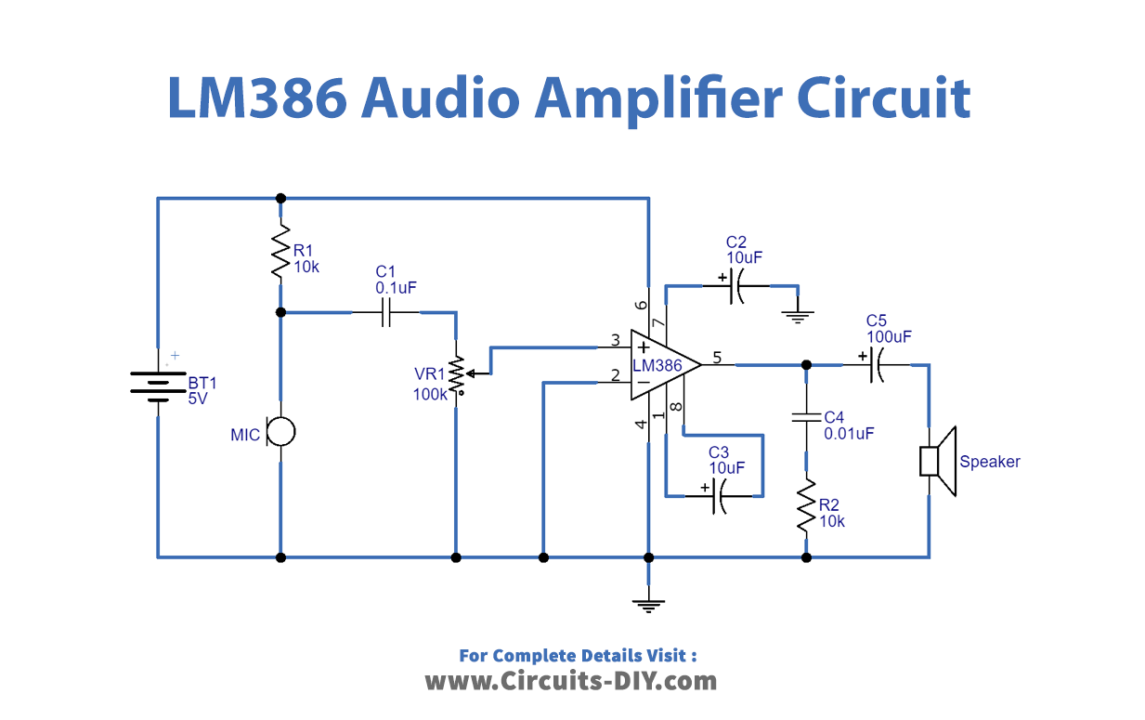
Working Explanation
In this LM386 Audio Amplifier Circuit 5V of supply is given at pin 6. Audio input is provided at the non-inverting input pin 3. A potentiometer is also wired to adjust the output audio. To set the gain of circuit 47uf of the capacitor is connected between pins 1 and 8. Output is coming at pin 5 where the capacitor is wired to drive the 8 ohms, speaker.
Application and Uses
- It can be utilized in Radio amplifiers.
- Also, in portable music players.
- In Audio booster circuits, etc.
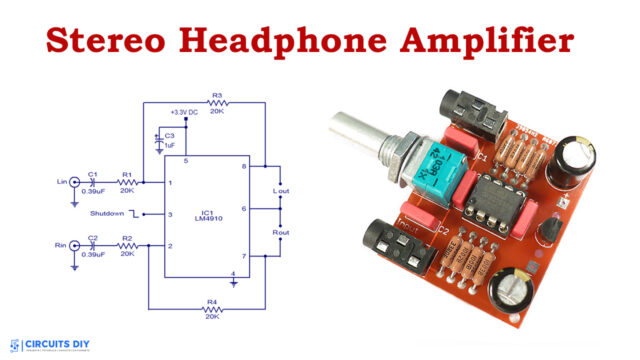
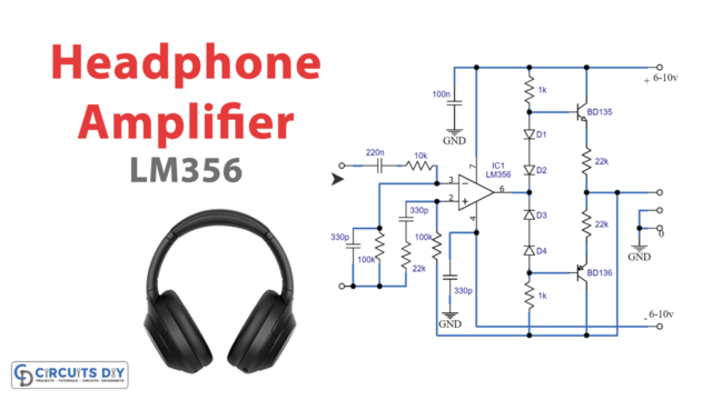


I know its not ideal, but could this be used to drive headphones?