Introduction
As we know that amplifiers are the circuits that convert a low signal into a high amplitude signal. But, most students don’t know that there are two types of amplifiers. A power amplifier and a pre-amplifier. So, today we are going to make a pre-amplifier circuit. Now, let’s overview what is a preamplifier.
Stereo Preamplifier
The central element that we are using for our circuit is LM3161. It is a two-channel preamplifier. Certainly, used for car stereo. The IC has an impedance of 100K. Moreover, it has a very less noise level. Also, it doesn’t require a greater number of components. Know that the maximum input voltage can be 18V. Hence, you may use 12 V for this circuit.
A stereo preamplifier is an amplifier that transforms the weak signal into a strong signal, but it’s not the final output stage. It then gives its output to a power amplifier for further proceeding to give the final output to the speaker (load). Hence, it removes noise and distortion of the input signal. Also, strengthen the input signal.
Hardware Components
The following components are required to make Stereo Preamplifier Circuit
| S.no | Component | Value | Qty |
|---|---|---|---|
| 1. | Power supply | 12V | 1 |
| 2. | PCB Board | – | 1 |
| 3. | IC | LA3161 | 1 |
| 4. | Resistor | 100 ohms, 150 ohms, 7.5K, 100K | 2, 1, 2, 2 |
| 5. | Capacitor | 0.015uf, 10uf, 47uf, 47uf, 1000pf | 2, 4, 2, 1, 2 |
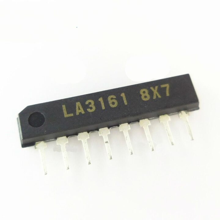
LA3161 Pinout
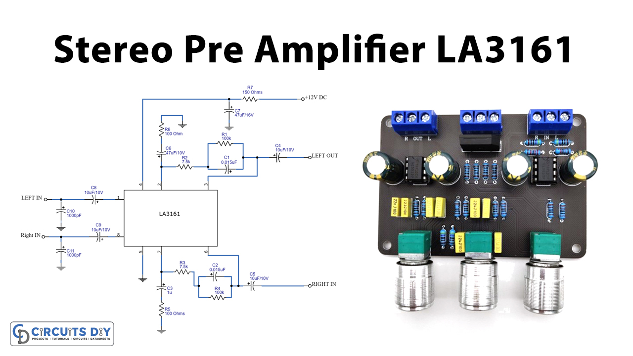
Stereo Preamplifier Circuit
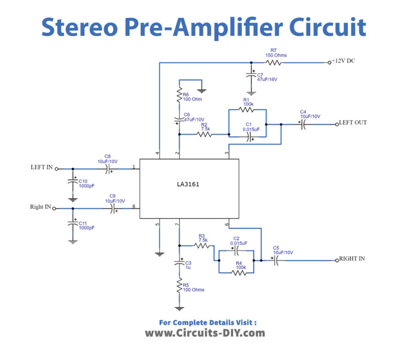
Working Explanation
The capacitors C10 and C11 are in the circuit to filter the noise. C8 and C9 are the input coupling capacitors. C7 is the power supply filter capacitors that should be placed very near pin 4.R2, R1, and C1 together interpret the frequency characteristics of the left channel. In the same vein, R3, R4, and C2 interpret the frequency characteristics of the right channel. Lastly, C4 and C5 are working as output coupling capacitors.
Applications and Uses
- It’s used as the first stage of an instrument amplifier.
- Utilized in electrode microphones, etc.