Introduction
In our various previous articles, we have discussed different amplifier circuits of different power. In this Tutorial, we will make a “40W transistor audio amplifier circuit with PCB”. The 40W transistor audio amplifier circuit is a powerful and versatile amplifier that can be used to amplify a variety of audio signals. The circuit features two transistors, an NPN and a PNP, which work together to create a high-powered amplifier. The amplifier is easy to build and can be easily modified to suit your specific needs. If you want to make your amplifier or upgrade existing ones, the 40W transistor audio amplifier circuit might be perfect.
This audio amplifier circuit is very easy to build, even for those with limited experience in electronics. The circuit is small and compact, making it a great choice for applications where space is at a premium.
Hardware Required
| S.no | Component | Value | Qty |
|---|---|---|---|
| 1. | NPN Transistor | MPS9632/BC547 | 3 |
| 2. | PNP Transistor | MPSA56 | 3 |
| 3. | Power Transistor | MJ2955 | 1 |
| 4. | NPN Transistor | 2N3055 | 1 |
| 5. | NPN Transistor | MPSA06 | 3 |
| 6.. | Resistor | 10K, 7.5K, 3.3K, 1.2K, 27K, 0.5Ω, 10Ω, 100Ω, 150Ω, 220Ω, 470Ω, 680Ω | 4, 1, 1, 1, 1, 2, 1, 2, 1, 2, 1, 1 |
| 7. | Electrolyte Capacitor | 10uF/16V, 47uF/16V, 47uF/50V | 1, 1, 2 |
| 8. | Ceramic Capacitor | 680pF/50V, 0.1uF/63V | 1, 1 |
| 9. | Variable Resistor | 1K | 1 |
| 10. | Diode | 1N4148 | 2 |
| 11. | Speaker | – | 1 |
| 12. | Zener Diode | 15V 0.5W | 1 |
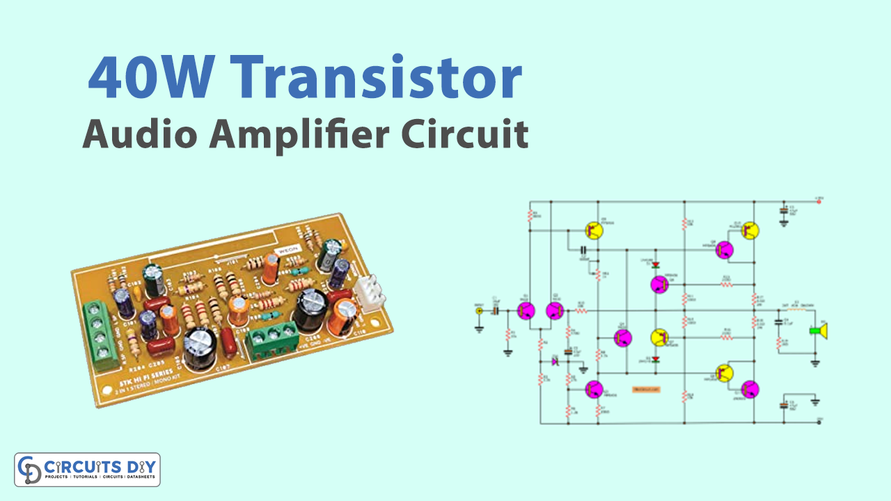
Circuit Diagram
Working Explanation
In this 40W Transistor Audio Amplifier Circuit with PCB, the transistors Q1 and Q2 of the MPS9632 work as a differential amplifier, while R10, R4, and C2 form the feedback circuit that determines a circuit’s overall gain ratio. The Zener diode is linked as a means of maintaining a consistent 15V voltage at the emitter circuit. The oscillator’s very high frequency is prevented by the feedback between the pin base and collector provided by transistor Q5, which is a component of the second amplifier circuit.
Transistors Q8 and Q9 serve as the driver circuit for Q10 and Q11, the power transistors (2N3055). Q7 serves as a circuit to safeguard Q6’s output transistor from harm. The typical bootstrapped circuit that makes use of the RC employs Q3 to restrict current. Since Q4 controls the output transistor’s bias level rather than using diodes as in a typical amplifier circuit, Additionally, this connection lessens crossover distortion.
Application Uses
- The transistor audio amplifier circuit could be used to amplify audio signals in a variety of settings, including homes, offices, and vehicles.
- It is compact and efficient, making it ideal for use in portable applications.