Introduction
In our daily life, we use numerous devices that use a transistor as an amplifier. Certainly, the main purpose of a transistor amplifier is to raise or enhance weak input signals. Nowadays, In the age of modern technology, we all have seen devices that amplify signals. For example, The most common use of a transistor amplifier circuit is a mic. But, many other devices also use this amplifier circuit. Moreover, as a student of electronics, you have also used these amplifiers in modulators and oscillators, etc. The circuit is not very hard to assemble. However, it is necessary to bias the transistor properly to work as an amplifier mode.
So, in this article, we are making the transistor amplifier. Make sure to assemble the circuit on a Vero or PCB board. For powering the circuit try not to use the main adapters, it would induce noise. The circuit uses electrolytic capacitors, rated between 10 to 15 Volts. A speaker which is wired as an output load must have an impedance of 64 ohms or more.
Hardware Required
| S.no | Component | Value | Qty |
|---|---|---|---|
| 1. | Vero/ PCB Board | – | 1 |
| 2. | Transistor | 2N2222 | 3 |
| 3. | Electrolyte Capacitor | 22uf, 100uf, 220uF | 2, 1, 1 |
| 4. | Ceramic Capacitor | 0.01uF | 1 |
| 5. | Resistor | 2.2K, 5.6K, 3.3K, 15K, 270K, 560K | 1, 1, 1, 1, 1, 1 |
| 6. | Speaker | 64 ohms | 1 |
| 7. | DC supply | 9V | 1 |
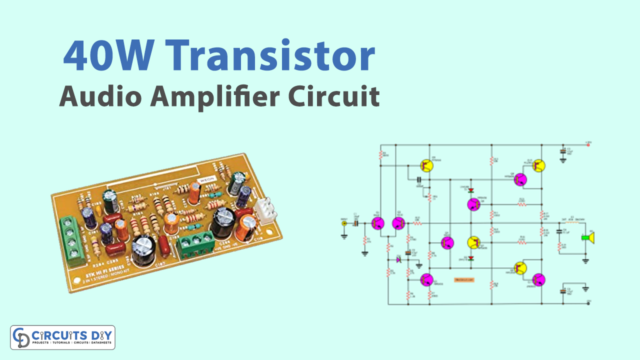
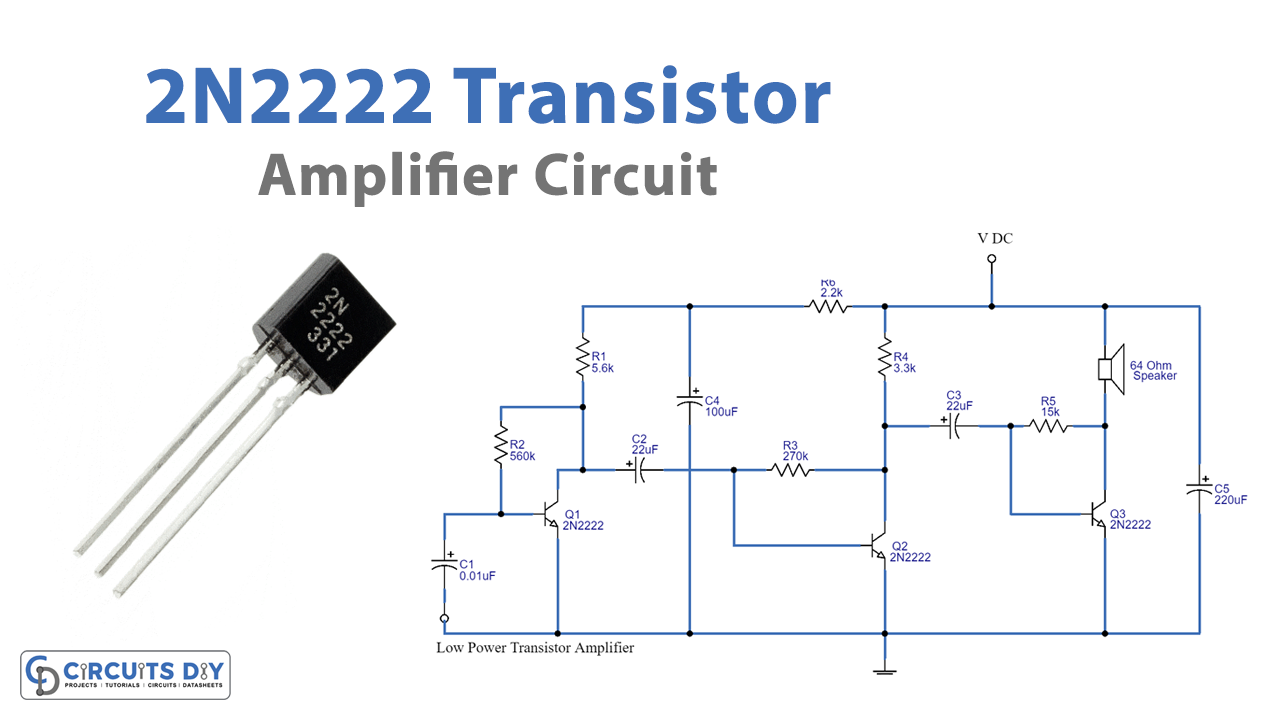
Circuit Diagram of Transistor Amplifier
Working Explanation of Transistor Amplifier
Firstly, to understand the circuit, we need to understand the biasing resistors. On operating the transistor, the collector voltage is a phase opposite to the input voltage. Hence, there is a resistor between the collector and the base. So, on operating the amplifier some percentage of the opposite collector voltage is given back to the base through Resistance. Therefore, this resistance is called biasing resistance. In this circuit, R2, R3, and R5 are working as bias resistors for transistors Q1, Q2, and Q3 respectively. Biasing resistors decreases the voltage gain. But on the other side, it increases stability. Now, coming towards the working. Q1 is wired with Q2 in a way that the base of Q1 is connected to the collector of Q2. In the same vein, the base of Q2 is wired with the collector of Q3. This coupling of the transistor increases or amplifies the voltage signal. This voltage signal is then filtered by capacitors C4 and C5. As a result, the amplified signal can be heard by the speaker in the circuit.
Application and Uses
- Above all, radio signals use these amplifier circuits
- Also, for long-distance communication system
- In conclusion, any circuit that needs amplification of signals can utilize this