Introduction
Step into the world of wonder and creativity with our exciting new blog! Get ready to dive into the world of electronics with this tutorial on the Simple Logarithmic Amplifier Circuit!
In this article, we’ll explore the ins and outs of this innovative circuit and discover how we can use it in various applications. From the circuit diagram to its working principle, we’ll break down every aspect of this circuit in simple, easy-to-understand terms. So buckle up and get ready to discover the excellent capabilities of the Simple Logarithmic Amplifier Circuit!
Hardware Required
You will require the following hardware for the Logarithmic Amplifier Circuit.
| S.no | Components | Value | QTY |
|---|---|---|---|
| 1 | IC | A1 to A4 IC 1 = 324, IC2 = CA3086 | 1 1 |
| 2 | Resistor | 100k, 27k, 2k2, 1k, 6k8, | 2, 2, 2, 1, 1 |
| 3 | Variable Resistor | 50k, 100k | 1, 1 |
What is Logarithmic Amplifier Circuit
The logarithmic amplifier circuit is an effective way to produce an output voltage that corresponds to the logarithm of the input voltage. It is a versatile circuit with various applications in various industries, including weather stations and remote control systems. In this article, we will take a closer look at the working principle of this circuit, its input/output characteristics, and its various applications.
Circuit Diagram

Working Principle of the Logarithmic Amplifier Circuit
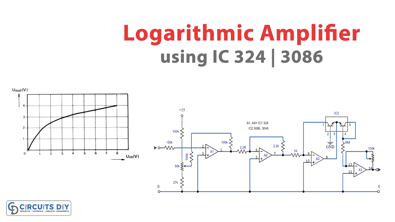
The circuit comprises operational amplifiers A1, A2, A3, and A4, transistor array IC2 and two potentiometers (P1 and P2). A1 and A2 form a non-inverting pre-amplifier that provides high amplification for small input voltages. The amplification decreases as the input voltage increases, and the output voltage eventually becomes almost static.
A3 and IC2 constitute the logarithmic part of the circuit, where the voltage at pins 4 and 5 of the array is logarithmically related to the output signal of A2. We can adjust the input level of circuit P1, which works as a high-impedance input buffer for A3.
A4 is the output stage of the logarithmic amplifier circuit, which amplifies the inverted signal from A3. The amplification factor of this stage can be altered using a preset potentiometer (P2) to match the output of the circuit to the load. To preset P2, we can connect a multimeter to the output of the circuit, and a signal at the maximum level can be applied to the input. P2 can then be adjusted to the required output voltage.
Input/Output Characteristics of the Logarithmic Amplifier Circuit
We can best see the performance of the logarithmic operational amplifier from its input/output characteristic graph. As shown in the Figure below, for small input voltages, the amplification is high, but as the input voltage increases, the amplification drops off, and the output voltage becomes almost static.

Applications of the Logarithmic Amplifier Circuit
The logarithmic amplifier circuit has a wide range of applications in various industries. For example:
- We can use it to drive a graphic recorder in weather stations
- Moreover, in remote control systems, it can prevent sudden and strong deflection of a servo arm.
- Additionally, the circuit is highly flexible, and we can use it with both analog instruments and a row of LEDs connected to its output.
Final Words
The logarithmic amplifier circuit is a simple yet powerful circuit that can produce a precise logarithmic output voltage. Its versatility and flexibility make it a popular choice in various industries, and its input/output characteristics make it an effective solution for applications that require high amplification for small input voltages. Try this circuit, and feel free to ask questions in the comment section. We would love to hear from you!