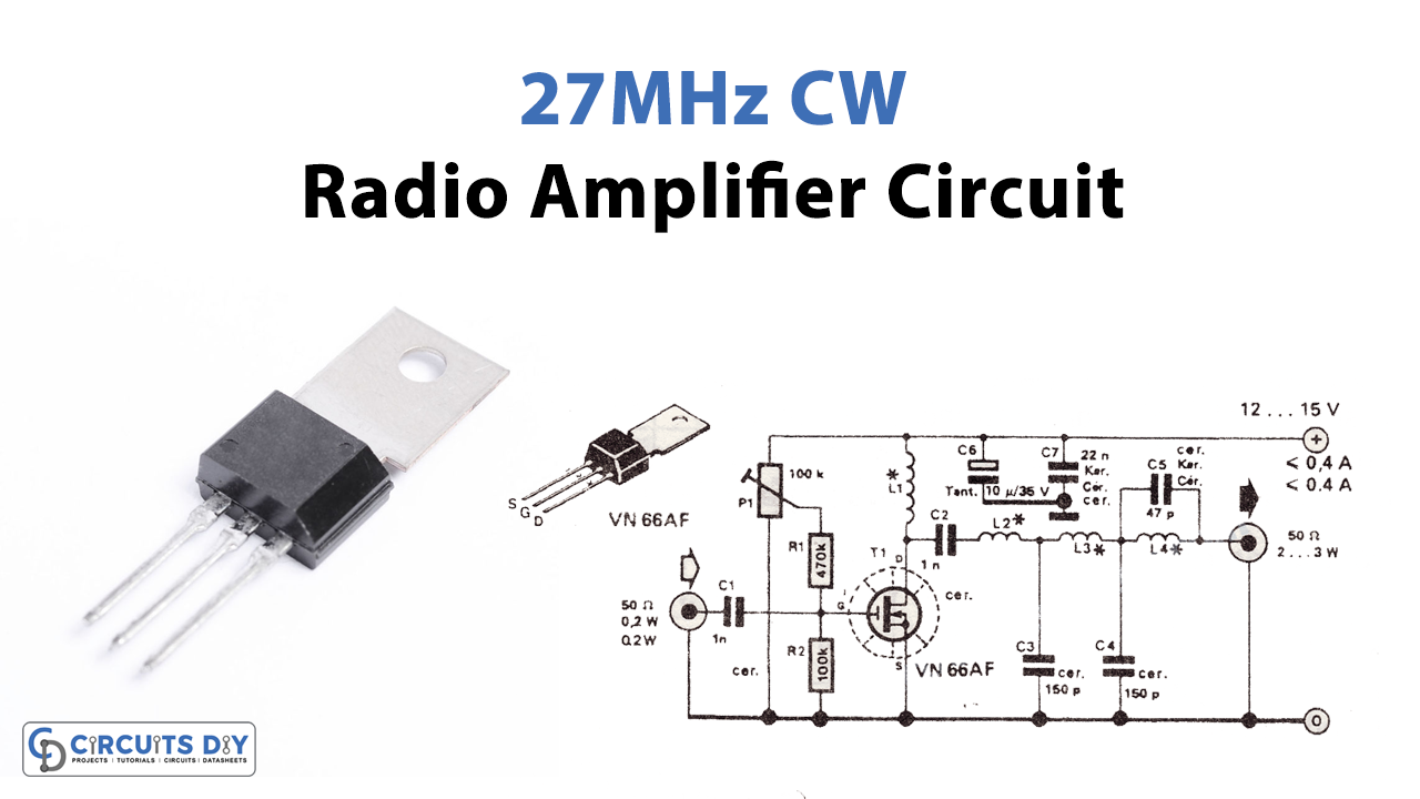
There is a wide range of sizes, efficiencies, and technological foundations from which to choose when shopping for a power amplifier. CW power amplifiers are distinguished from other amplifiers by their distinct capabilities.. So, to understand the differences, in this tutorial, we will make a “27 MHz CB radio amplifier circuit.”
A Siliconix VN66AF transistor is used in the 10-meter 27 MHz CW radio amplifier, along with a few other parts, because it is cheap, has good dielectric insulation, and has a high gain.
What are CW Amplifiers?
As their name implies, continuous wave amplifiers (CW amplifiers) amplify weak signals while preserving their original waveform. Continuous wave amplifiers are an excellent choice for applications needing constant RF or microwave field intensity. Given a constant supply voltage, a CW amplifier will constantly draw current. Amplifier input-signal strength, maximum output power, and load affect how much current it draws.
Hardware Required
| S.no | Component | Value | QTy |
|---|---|---|---|
| 1. | V-MOSFET Semiconductor | VN66AF | 1 |
| 2. | Resistor | 470K, 100K | 1, 1 |
| 3. | Ceramic Capacitor | 1nF, 22nF, 47pF, 150pF | 2, 1, 1, 2 |
| 4. | Electrolytic Capacitor | 10uF | 1 |
| 5. | Inductor | 5 turns/1mm, 8 turns/1mm, 12 turns/0.6mm | 2, 1, 1 |
| 6. | Variable Resistors | 100K | 1 |
Circuit Diagram

Working Explanation
We use the VN66AF as a 10m band RF amplifier in this CW amplifier circuit. This 27MHz rf amplifier can turn low-power transmitters into powerful 10m transmitters with an output power of 2-3 watts or more. The attenuation of the band-pass filter is guaranteed to be at least 55 dB.
The gate current of a VMOS FET must be set to 20mA and modified with P1 for linear applications. To utilize the 10m rf amplifier for FM and CW, we must set P1 to ground.
Application Uses
- Testing devices
- Automotive industry
- Aerospace applications