Introduction
In this tutorial, we are going to make a “Medium Impedance Preamplifier circuit using a transistor”. One property of electronic circuits that measures resistance to a current is impedance. Impedance, however, might be high, medium, or low. In this article, We are attempting to get medium impedance. Thus, to get the medium impedance for our amplifier circuit, we will be using a common emitter configuration of the transistor.
In a common emitter, the Base is the input, Collector is the output terminal, and the Emitter is the common terminal both for the base and collector. That is, the base and common emitter terminals are input terminals, whereas the collector and common emitter terminals are output terminals.
Hardware Required
| S.no | Components | Value | QTy |
|---|---|---|---|
| 1 | Transistor | BC549 | 1 |
| 2 | Resistor | 1M, 4.7K, 100 ohms | 1, 1, 1 |
| 3 | Capacitor | 47uF, 4.7uF, 100uF | 2, 1, 1 |
| 4 | Variable Resistor | 470 ohms | 1 |
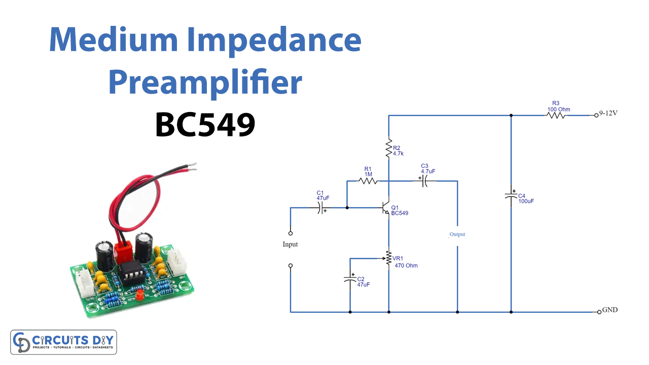
Circuit Diagram

Working Explanation
Since this Medium Impedance Preamplifier circuit follows the common emitter configuration where input is fed through the base of the transistor and the output is taken at the collector pin. The power supply is given to the circuit with the help of resistor R3 and capacitor C4. Then it applies a positive voltage to Q1’s lead collector with R2 acting as a load for this part.
Now to pass the voltage from the collector to the base, we use the feedback technique. It is a biasing technique that can be varied depending on the power source of the circuit. Potentiometer VR1 is there to act as a bias on the emitter pin. Capacitor C2 is used to bypass the gain ratio. By adjusting the bypass point, you may change the gain based on the audio source’s input.
Application Uses
- This circuit can be typically used in amplifiers that require a medium amount of impedance.