Introduction
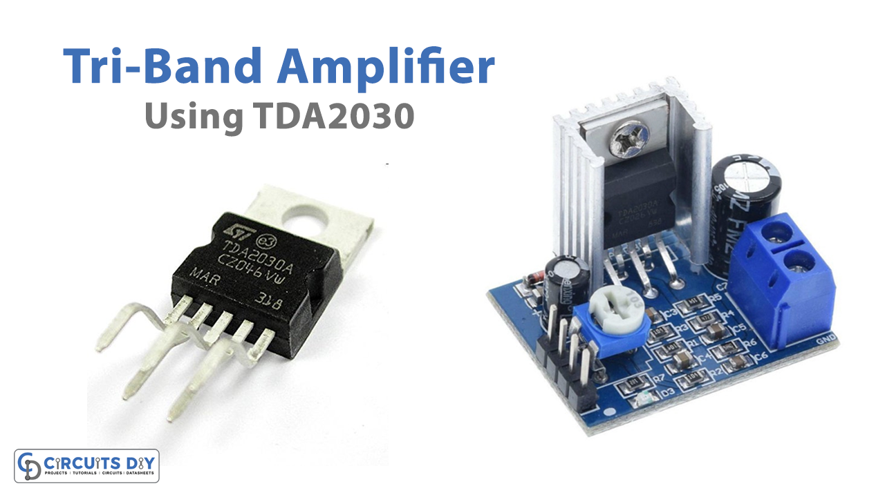
In this tutorial, we are going to make a “Tri-Band Amplifier Circuit using TDA2030”. Tri-band is a technology that can often work on three frequencies rather than just one. Therefore, the circuit uses three amplification ICs. Thus, provides three outputs power ranges, having different cut-off frequencies:
- For the woofer’s low-frequency range, cut off at 300Hz.
- The midrange cut off at 3 kHz.
- And the frequency that surpasses 3KHz is considered high.
Hardware Required
| S.no | Component | Value | Qty |
|---|---|---|---|
| 1. | IC | TDA2030 | 3 |
| 2. | Resistor Different Values | – | 23 |
| 3. | Capacitor Different Values | – | 24 |
| 4. | Speaker | 4 ohm,4-8 ohm | 1,2 |
| 5.. | Diodes | 1N4001 | 6 |
| 6. | Bridge Rectifier Diodes | BC5000, 3500 | 4 |
| 7. | Transistor | BC239 & 240C | 1,1 |
Circuit Diagram
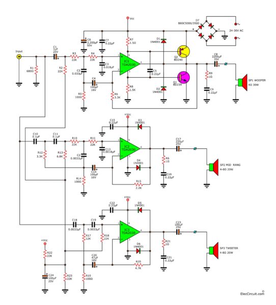
Working Explanation
The circuit looks a little complicated but, we will try our best to explain this to you. Since there are three outputs of different ranges coming from three different speakers. These outputs are:
- Woofer
- Mid Range
- Tweeter
Now let us understand their explanations one by one.
Woofer Sound
For this sound, first, there is a resistor R1, connected between the input and output, providing constant input impedance. The capacitor C1 is responsible for coupling the input signal to a low-pass filter. Resistors R3, R4, and capacitors C2, and C3 make up the low pass filter. The signal from this filter circuit will be of low frequency, less than 300 Hz.
The signal is then sent into TDA2030 IC1, which amplifies it and drives transistors Q1 and Q2. Resistors R7 and R8 are there to bias transistors Q1 and Q2. Resistor-R6 serves as a feedback resistor. Capacitors C4 and R5 are dividers. R9 and C9 are both acting as load in this part of the circuit. C8 serves as a coupling output capacitor to operate the woofer speaker.
Mid-Range Sound
Capacitors C10, C11, C12; Resistors R10, R11, and Capacitors C12, make up the signal of mid-range frequency. The signal is then sent into TDA2030 IC2, which amplifies this signal. Capacitor C17 works as a load at this part of the circuit.
Tweeter Sound
This section of the circuit has a high pass filter, which is made up of C18, C19, and R17. The signal from this filter is sent to the input of IC3, which acts as an amplifier to boost the signal. The R20 resistor is a feedback resistor. C20 and R19 are the divider feedback voltages. The divider circuit is made up of R22 and R23. To divide the voltage over half of the power supply circuit. And C24 keeps the voltage steady and stable. This voltage is a biassed voltage applied to the input (pin 1) of ICs 1, 2, and 3. The R21 and C21 are load circuits, while the C23 serves to couple the output signal to the Tweeter speaker.
Application Uses
- In the bass amplifier circuits
- To produce trouble sound for audio signals.
- For the amplification of high, low, and mid-range frequencies.