Introduction
In the electronics devices world, amplifiers have their special place and maybe that is the reason, they are widely used. These are the circuits that strengthen the signals coming from input. They have great application in many industries including automotive and entertainment. We always try to make different amplifier circuits for you all and hence in this tutorial we are here again with another amplifier circuit.
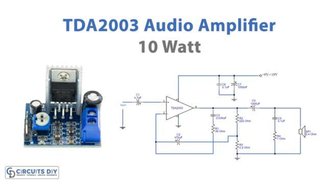
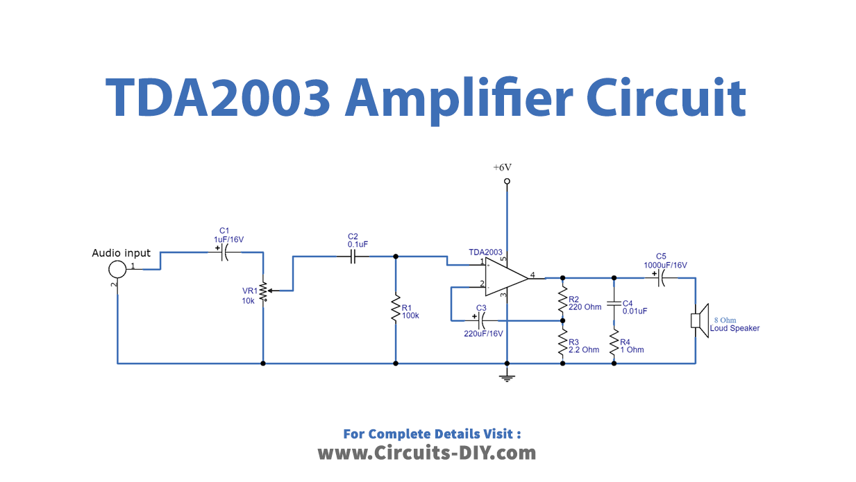
So, we are going to make a “TDA2003 Amplifier Circuit Diagram”. it uses the integrated radio amplifier TDA2003. The IC is reasonable and inexpensive. It provides short circuit protection. And, have low crossover distortion. To make the circuit, remember to use a good-quality board. Also, use the heat sinks as the IC dissipates some heat. A 12V DC power supply can also operate the circuit.
Hardware Required
| S.no | Component | Value | Qty |
|---|---|---|---|
| 1. | IC | TDA2003 | 1 |
| 2. | Speaker | 8Ω | 1 |
| 3. | Potentiometer | 10KΩ | 1 |
| 4. | Electrolysis Capacitor | 1000μF, 220μF, 1μF | 1, 1, 1 |
| 5. | Ceramic Capacitor | 0.1μF, 0.01uF | 1, 1 |
| 6. | Resistors | 100K, 1Ω, 2.2Ω, 220Ω | 1, 1, 1, 1 |
| 7. | Battery | 12V | 1 |
| 8. | 2-Pin Connector | – | 2 |
Circuit Diagram
Working Explanation
In this TDA2003 Amplifier Circuit, first, you need to connect the audio input signal to the non-inverting pin of the TDA2003 IC. There is a potentiometer is working as a volume control. The Inverting pin of an ic is wired with capacitor C3 and divider Resistors R2 and is working as a feedback path. At the output, we connect the loudspeaker with the help of a coupling capacitor.
Application and Uses
- Car audio amplifiers.
- Electronic audio instruments.
- public addressing systems, etc