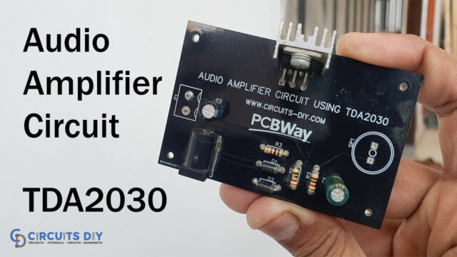
Introduction
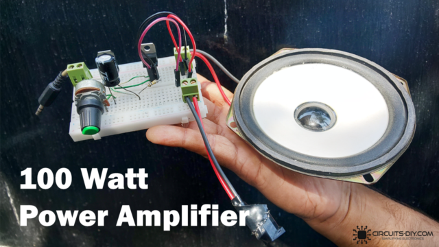
In this Tutorial, we are going to make a “TDA2003 10W audio amplifier circuit”. The integrated amplifier TDA2003 is used in the circuit. The IC is quite affordable. Additionally, it offers protection against short circuits. Moreover, minimize crossover distortion. Use a durable board for building the course. Also, Use the heat sinks because the IC emits some heat. A 12V DC power source can also be used to power the circuit. The amplifier itself has a massive open-loop gain and highly stable construction. Hence, The power amplifier needs extra components for either feedback, decoupling, or high-frequency suppression.
Hardware Required
| S.no | Component | Value | Qty |
|---|---|---|---|
| 1. | IC | TDA2003 | 1 |
| 2. | Resistor | 39 ohm,1 ohm, 220 ohm, 2.2 ohm | 1, 1, 1, 1 |
| 3. | Electrolyte Capacitor | 4.7uF, 470uF, 1000uF | 1, 1, 2 |
| 4. | Ceramic Capacitor | 0.1uF, 0.039uF | 2, 1 |
| 5. | Speaker | 2 ohm-8 ohm | 1 |
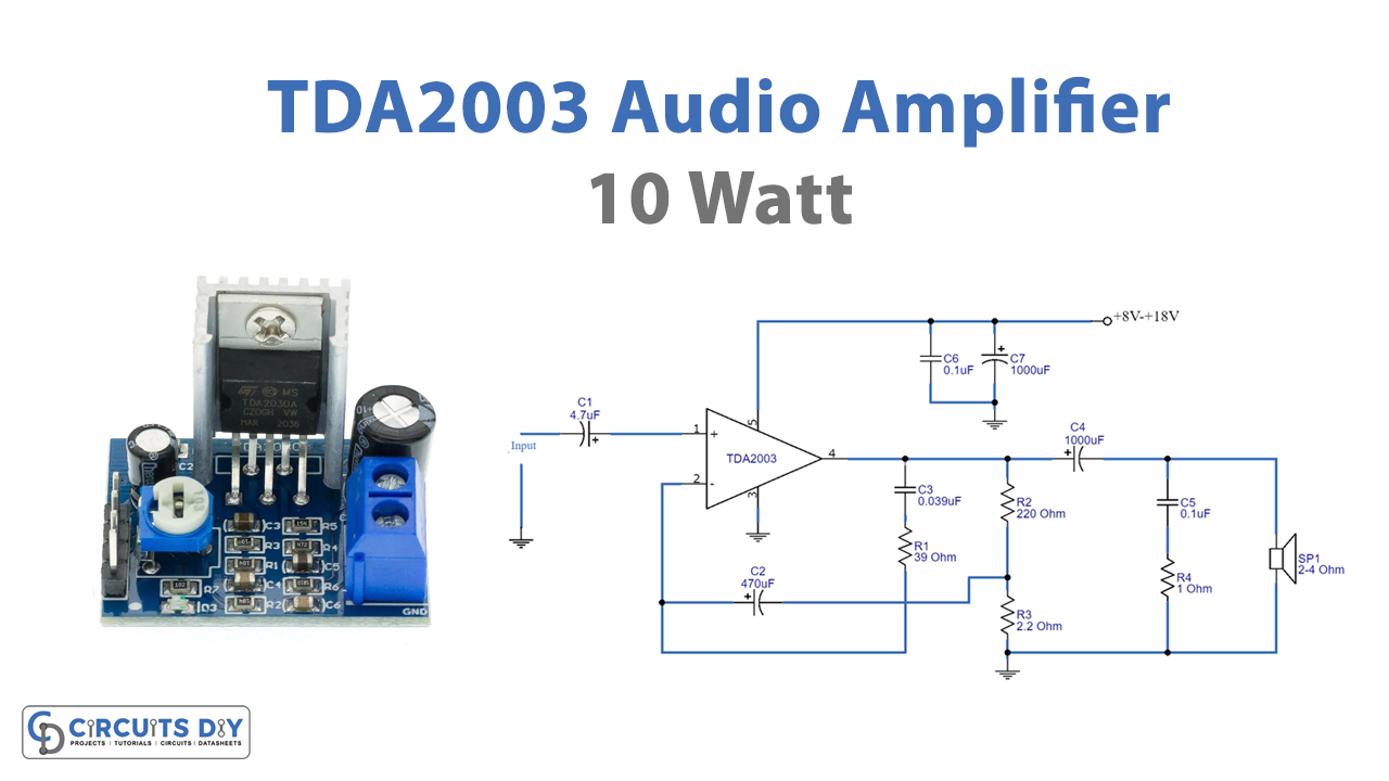
Circuit Diagram

Working Explanation
When we provide the power supply, the TDA2003 10W Audio Amplifier Circuit receives 15V. To change the volume, the C1 couples an audio signal through the potentiometer VR1. Afterward, the C2 transmits an anti-noise DC input signal to pin 1 of an IC. The output of an IC comes from pin 4. Capacitor C5 improves low-frequency response stability. R4 and C6 will also disperse the sounds to the ground before sending them to the speakers. A further portion of the output signal is transmitted back through C3, R1, and pin 2’s inverting pin to keep the frequency response at -3dB constant. There is a filter capacitor called C8. Noise from the power supply was removed using C7.
Application Uses
- Car audio amplifiers
- Music amplifiers
- Public Addressing systems
- Stereo amplifiers, Etc