Introduction
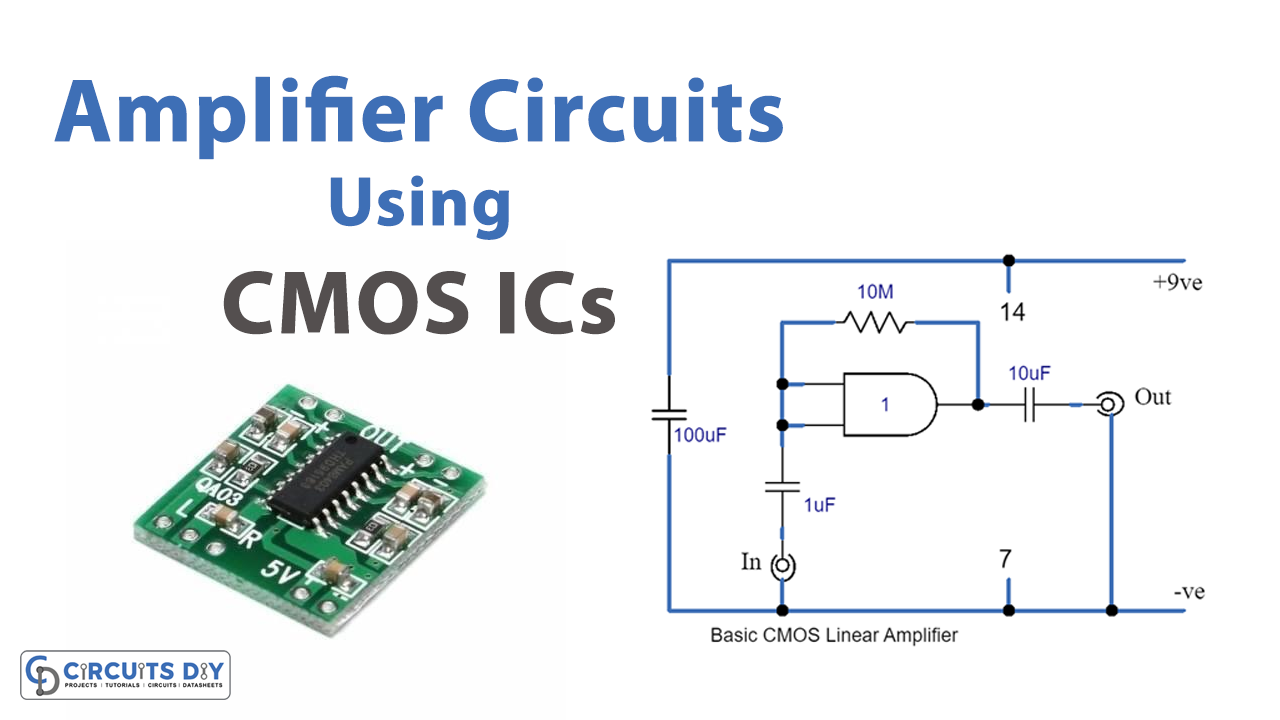
Amplifier circuits play a crucial role in many electronic systems, from boosting signals in audio equipment to amplifying signals in communication systems. One of the most popular options for building amplifier circuits is the use of complementary metal-oxide-semiconductor (CMOS) integrated circuits (ICs). In this tutorial, we’ll take a hands-on approach and show you step-by-step how to build amplifier circuits using CMOS ICs. From understanding the essential circuit components to building and testing your amplifier circuit, this guide is packed with practical information to help you get started with CMOS amplifier circuits. So, let’s get started!
Hardware Required
You will require the following hardware for Amplifier Circuits Using CMOS ICs.
fig 1 Circuit table
| S.no | Components | Value | QTY |
|---|---|---|---|
| 1 | IC | IC1 | 1 |
| 2 | Polar Capacitor | 1, 10, 100uF | 1, 1, 1 |
| 3 | Resistor | 10M | 1 |
Circuit Diagrams
Basic CMOS Linear Amplifier
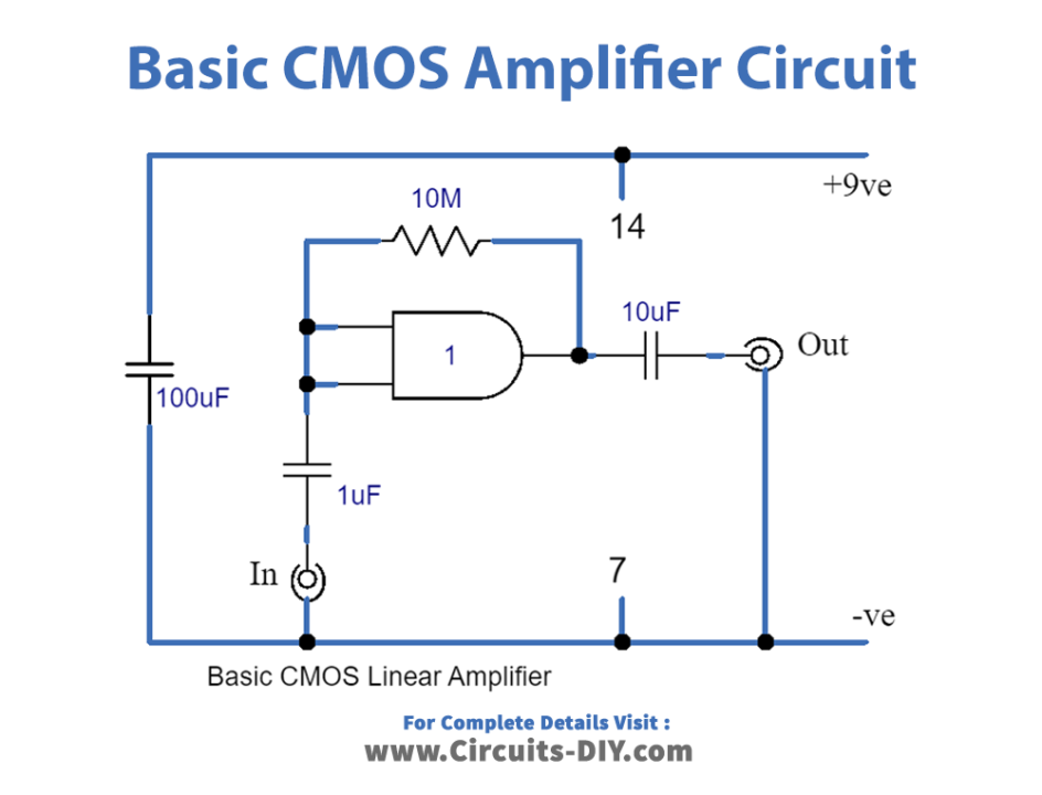
fig 2 Circuit Table
| S.no | Components | Value | QTY |
|---|---|---|---|
| 1 | IC | – | 3 |
| 2 | Polar Capacitor | 10, 100uF | 1, 1 |
| 3 | Non Polar Capacitor | – | 1 |
| 4 | Resistor | – | 2 |
Advanced Amplifier
Working Explanation
Basic CMOS Linear Amplifier
Here’s the explanation rephrased in a beginner-friendly format:
The circuit diagram of a simple CMOS amplifier is shown in the figure below. It uses a single inverter and a resistor (R1) to bias the inverter as a linear amplifier. When the supply is first connected, the device’s output will start to go high because the input will be low.
Once the voltage at the output reaches the transfer voltage of the gate, the input will attempt to make the output low by taking the input high through the voltage acquired from the output via R1. This negative feedback activity will stabilize the output voltage at around half the supply voltage. The gate is now biased in a linear mode.
This circuit provides a voltage gain of about 50 times at audio frequencies. Even at frequencies in the MHz range, it will still provide some degree of gain. However, it is not suitable for use in Hi-Fi circuits and is best suited for non-critical applications, such as a peak level indicator.
The value of R1 is not critical, but it should be in the Megohm range for the full voltage gain of the circuit to be achieved. C1 and C2 are the input and output D.C. blocking capacitors, respectively. Using this circuit with a supply voltage lower than 9 V is not recommended as it may become unstable.
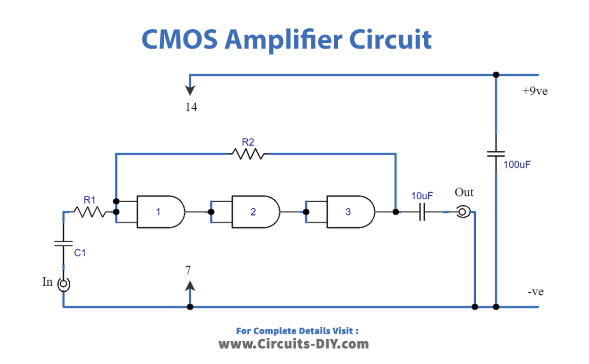
Advanced Amplifier
We can create a more advanced amplifier circuit by connecting three inverters in a row. The diagram below shows how this is done. The circuit is set to operate in a linear mode by resistor R2, which acts in a similar way to R1 in the “Basic CMOS linear amplifier” circuit.
We can use different amplifier configurations to choose the desired input impedance and voltage gain for the circuit. The circuit’s input impedance is equal to the value assigned to R1, and the value of R2 is calculated by multiplying R1 by the desired voltage gain.
While it’s possible to get high input impedances in the Meg ohm range and high voltage gains, it’s not possible to get both at the same time. This is because a high-value resistor is needed for R2, but it may not be readily available, and using a lower-value resistor may result in instability.
This advanced circuit has an open-loop gain of 125,000 times (since the gain of one is 50, and therefore 50 x 50 x 50 = 125,000). When used in practical situations, it has a closed-loop gain of around 10 to 20, and negative feedback is applied to the circuit. This makes the circuit efficient in reducing noise and distortion, but it’s unsuitable for high-quality sound applications. To avoid instability, it’s important to use a component layout that’s free from excessive stray capacitances, especially when using an input impedance of more than a few kOhms.
Final Words
In conclusion, CMOS ICs can be used to create simple and advanced amplifier circuits. The basic CMOS linear amplifier uses a single inverter and resistor R1 to bias the circuit into a linear operating mode. While the circuit provides a voltage gain of around 50 times, it’s best suited for non-critical applications.
A more advanced amplifier can be created by cascading three inverters together, allowing greater input impedance and voltage gain, making it efficient in reducing noise and distortion but unsuitable for high-quality sound applications.
While CMOS ICs offer versatility and convenience in amplifier circuit design, it’s important to consider the limitations and characteristics of the circuits to ensure they meet the intended requirements and applications.