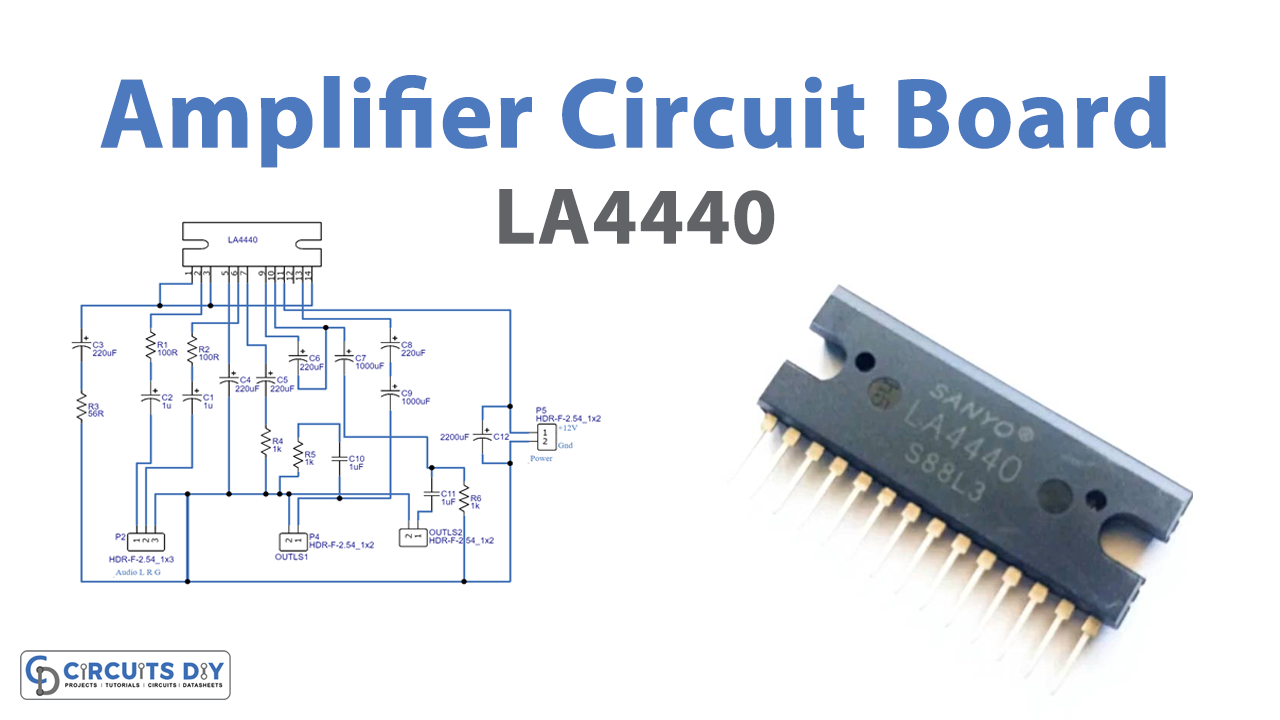
In this tutorial, we are going to make a “LA4440 Amplifier Circuit Board”.
An amplifier is an electronic device, that can increase the power of a signal. If you are listening to music or movies on laptops and computers, laptop speakers are never loud enough to give satisfying listening. They give users the ability to hear something but for anything like music or movie soundtracks, they are very poor performers. The output from laptop built-in speakers is just too low. Here LA4440 is a dual channel 6W monolithic linear IC audio amplifier, this amplifier IC is most suitable for low-power audio applications. It has a good ripple rejection of 46dB and good channel separation.
This IC gives low distortion, over a wide range from low frequencies to high frequencies. It has a built-in thermal protector however, it is better to use a heat sink. LA4440 has an overvoltage, surge voltage protector, and pin-to-pin short protector. These specific features make the LA4440 a unique audio amplifier. Now by using a built-in dual channel, we can amplify stereo audio signals and make bridge amplifier applications. It will give 6W output, when in the dual stage and gives 19W in the bridge stage. The circuit uses a LA4440 and some supporting components, to give you much more power while retaining a small package that you can use.
Hardware Required
| S.no | Component | Value | Qty |
|---|---|---|---|
| 1. | Amplifier IC | LA4440 | 1 |
| 2. | Resistor | 56Ω,100Ω,1KΩ | 1,3,2 |
| 3. | Capacitor | 220uf,1000uf,1uf,2200uf | 4,2,4,1 |
| 4. | Header Male | 2.54 1*2 | 4 |
| 5. | Connecting Wires | – | – |
| 6. | Battery | 12V | 1 |
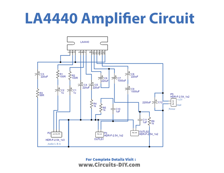
Circuit Diagram
Working Explanation
As we can see in the circuit, the main part of the circuit is LA4440 IC. Here Vcc is applied as +12V, recommended load resistance for stereo is 2 to 8 ohms and for the bridge is 4 to 8 ohms. This amplifier gives 30K ohms input resistance. We can control the output volume, by adding an input variable resistor.
Now, this circuit is constructed in order to provide stereo amplification to the input audio signal. Therefore pin numbers 2 and 6 take audio input signals, and from pins 10 and 12 amplified output audio signals are taken out. We need the maximum supply voltage for this amplifier to be +18V, and it operates at -20 to +75 °C temperature.
Here needs a separate power supply circuit, as the PCB contains only an amplifier circuit. It can be used as a stereo amplifier breakout, connecting two 8 ohms of speaker for better audio output. Pin number 4 is an audio muting pin and is purposely opened. Pin number 8 is a power amplifier Gnd 2 (Gen 2), it is also purposely open. Use a bridge rectifier with regulated output for better response.
Application
It can be used as a breakout board, for audio amplification purposes.