Introduction
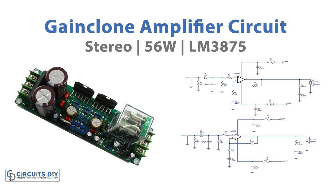
In this tutorial, we are going to make the “56W Gainclone Stereo Amplifier Circuit using LM3875”. Are you get worried about its name? The Gainclone idea is based on the original Kimura-San/47Labs Gaincard design, which follows the principle that “less is more” and has a low component count, a very short signal route, etc. According to Wikipedia, the Gaincard amplifier was introduced by 47 Labs in 1999. The Gaincard’s unusual design shocked the audiophile community. It was built more simply, with fewer components, and with less capacitance than anything that came before it. It used a 56-watt chip from National Semiconductor called the LM3875 for amplification.
With a generally low noise floor of 2.0 V, the LM3875 maintains a good signal-to-noise ratio of better than 95 dB. It has outstanding linearity and is exceptionally low.
LM3875 Features
- 6W continuous average output power into 8Ω
- 100W instantaneous peak output power capability
- Signal-to-Noise Ratio >95 dB (min)
- Output protection from a short to ground or to the
- supplies via internal current limiting circuitry
- Output over-voltage protection against transients from inductive loads
Hardware Required
| S.no | Component | Value | QTy |
|---|---|---|---|
| 1. | IC | LM3875 | 2 |
| 2. | Resistor | 1K, 33K, 120K, 47K, 0.1uF, 1 Ohm | 2, 2, 2, 2, 2, 2 |
| 3. | Capacitor | 10uF, 220pF, 0.1uF, 0.22uF, 22uF | 2, 2, 4, 2, 2 |
| 4. | Speaker | 4-8 ohm | 2 |
| 5 | Fuse | 2A | 4 |
Circuit Diagram

Working Explanation
There are two channels on this circuit; the left channel and the right channel. Here we will see the working of only one channel to understand both. So, let’s focus on the left channel. Here, resistor R2 acts as a set, and the coupling capacitor C2 makes the circuit’s impedance 33K. Coacior C3, Resistors R3, and R1 together make the ultrasonic filter circuit. Lower the RF signal before it enters pin 7 to protect it from radio noise and attenuate it. As a result, this has a high gain of 25 times.
Equation (1 + R5 / R6) is used to compute the gain that is sent from the input signal back to the input with the aid of resistors R5 and R6. In order to help decrease frequency to -3dB at a frequency of roughly 10Hz, the capacitor C5 is connected to R6. The signal is now amplified before exiting the IC at pin 3. The speaker must proceed to the Zobel network circuit before departing; which includes resistor R4 and capacitor C4, to fix the load capacity issue and keep stability at high frequencies.

The AC power’s voltage is decreased by the supply transformer. 5A of current is applied from high voltage 220VAC to low voltage. This low voltage is then transferred to the bridge rectifier BD, which boosts the voltage to around + 31 V DC. Capacitors C13 and C14 are there to smooth the voltage. It serves as the amplifier circuit’s supply voltage.
Application Uses
- It is suitable for Compact stereo.
- for speakers with self-power.
- Additionally, amplifiers for surround sound.
- High-end stereo televisions.