Brief Overview of TDA1524
This article is about “TDA1524 Stereo-Tone & Volume Control Circuit”.
The TDA1524A IC is designed as an active stereo control for Television receivers, mains-fed devices, vehicle radios, etc. It has controls for balancing, built-in volume control with contour, bass, and treble adjustment, and other features. Single linear potentiometers or d.c. voltages can both be used to regulate each of these functions.
This IC only needs a few extra parts. Due to inbuilt gain, the IC features low noise and a wide range of power supply voltage.
TDA1524 Pinouts

Hardware Required
| S.no | Component | Value | Qty |
|---|---|---|---|
| 1. | IC | TDA1524 | 1 |
| 2. | Resistor | 220 ohms, 2.2K, 4.7K | 2, 1, 2 |
| 3. | Electrolyte Capacitor | 10uF, 100uF, 22uF | 2, 1, 2 |
| 4. | Ceramic Capacitor | 0.015uF, 0.047uF, 0.22uF, 0.1uF | 2, 2, 1, 6 |
| 5. | Switch | – | 1 |
| 6. | Variable Resistor | 50K | 4 |
| 7. | Supply | 12V |
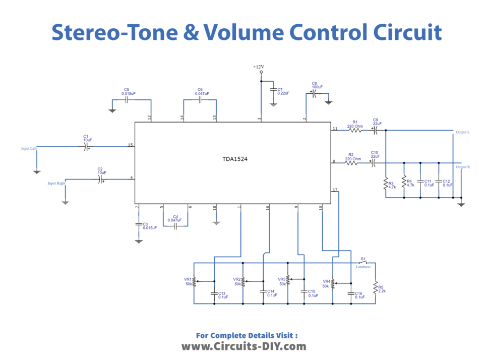
Circuit Diagram
Working Explanation
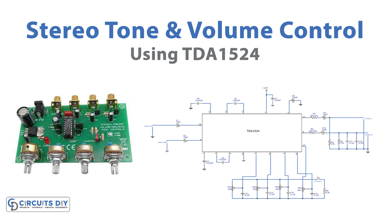
A single IC is used in this tiny stereo-tone control circuit. TDA1524A is working like a heart in this circuit. Now, first, a positive voltage from the power supply is applied to pin 3 of the IC, and a negative voltage is applied to pin 8. So, there aren’t many capacitors and resistors in this circuit. This circuit can be used to filter out a wide variety of various frequencies. When we connect an audio source’s signal to IC1’s pin 15, the input, signal passes through the left and right coupling capacitors, C1 and C2, of each channel. The mechanism inside the IC would then enhance the signals after that. We have used capacitors C6 and C4 to Control the frequency for a loudness function. With switch S1, we may toggle this feature on or off.
C5, C3, VR1, VR2, VR3, and VR4 make up the tone control section. Frequency controllers are the capacitors C5 and C3. The Volume, Balance, Bass, and Treble are each controlled by a separate potentiometer (VR1, VR2, VR3, and VR4).
After the signal gains strength and changes frequency. It will reach pins 8 and 11 on each channel’s audio IC. This has resistors R1 and R2 to adequately reduce the signal. The signal then passes via each channel’s coupling capacitor, C9, and C10, with R3 and R4 connected in series. Now, DC is removed from the scene entirely. Following that, capacitors C11 and C12l cancel out high frequencies greater than 70 kHz. Finally, we will have a perfect output.
Application Uses
- Tone-control audio systems
- Car radios
- Television Receivers