Introduction
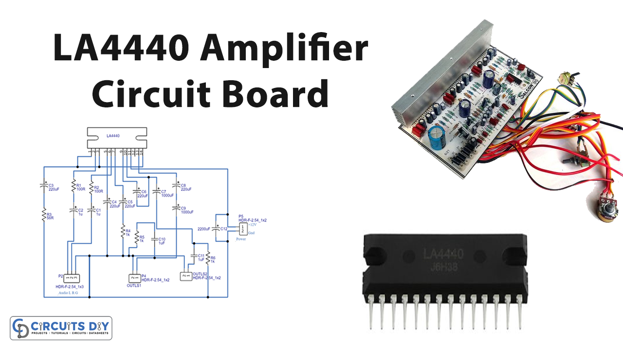
We have already discussed in so many articles that Audio amplifiers are circuits that convert low-power input audio impulses into high-power output audio signals. The circuits’ goal is to provide a noise-free, efficient, and low-distorted audio signal with a larger output magnitude. These amplifier circuits can be made in so many different ways. Here we are with another amplifier circuit. So, in this tutorial, we are going to “LA4440 Amplifier Circuit Board”.
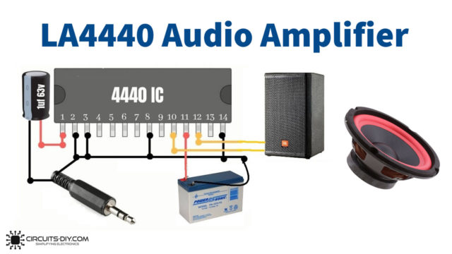
The LA4440 is a two-channel audio power amplifier IC with dual channels built-in, making it suitable for bridge and stereo amplifier applications. It produces 6 W per channel in dual mode and 19 W in bridge mode.
Features of LA4440
- This integrated circuit requires a minimum number of external components.
- It generates low pop noise when gets turned on or off
- It allows good ripple rejection of 46db
- Good channel separation.
- It produces very small residual noise
- It gives low distortion over a wide range of frequencies.
- Also, the Ic has a built-in audio muting function and built-in protectors.
- It has a thermal protector, overvoltage, surge voltage protector, and Pin-to-pin short protector.
Hardware Required
| S.no | Component | Value | Qty |
|---|---|---|---|
| 1. | LA4440 | – | 1 |
| 2. | Potentiometer | 1KΩ | 4 |
| 3. | Ceramic Capacitor | 1uF | 2 |
| 4. | Capacitor | 1uF, 220uF, 1000uF, 2200uF | 2,5,2,1 |
| 5. | Resistor | 100R, 56R, 1KΩ, | 3,1,2 |
| 6. | Battery | 12v | 1 |
| 7. | 2-Pin, 3-Pin Connector | – | 3,1 |
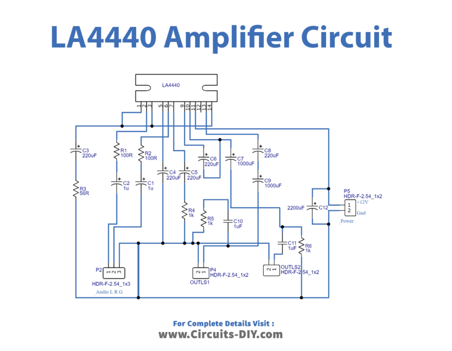
Circuit Diagram
Working Explanation
This LA4440 Amplifier Circuit is designed to offer stereo amplification to the audio input signal. Audio input signals are obtained from pins 2 and 6, while amplified output audio signals are collected from pins 10 and 12. This amplifier’s maximum supply voltage is +18V, and it can work in temperatures ranging from -20 to +75 degrees Celsius.
Vcc is set to +12V, and the suggested load resistance for stereo is 2 to 8 ohms, while for the bridge it is 4 to 8 ohms. This amplifier has a 30K ohm input resistance, and we can regulate the output loudness by adding an input variable resistor. For better reaction, use a bridge rectifier having regulated output.
Application and Uses
- For audio amplification.
- The circuit can also be used in electronic public address systems.