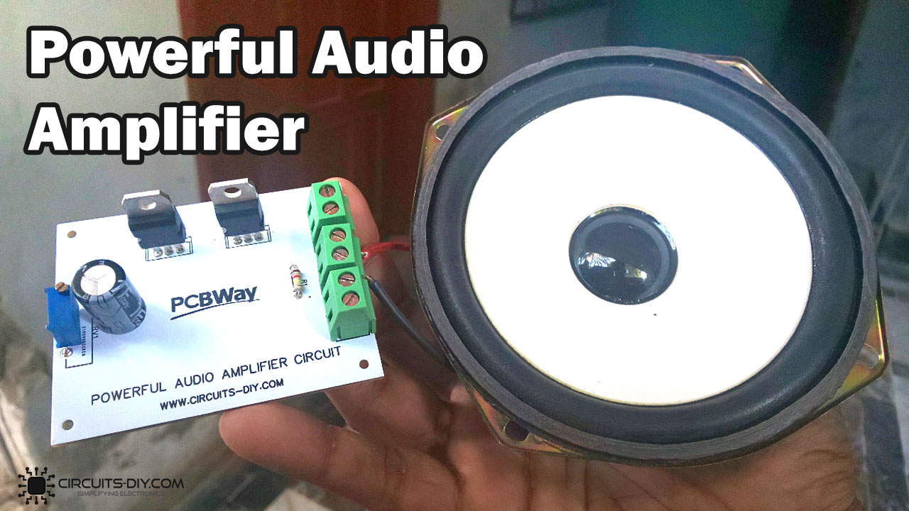
An audio amplifier is a simple electronic circuit that can be used to take in a weak audio signal and then transduce it into a better, more powerful, and audible audio signal.
Audio amplifiers are now seen in almost every consumer electronic product in some shape, way, or form. Some basic examples would be music players, camcorders, smartphones, laptops, and PCs. In today’s article, we are going to go over a step-by-step process on how to build a 100W Powerful Audio Amplifier using the TIP122/127 Darlington pair transistors.
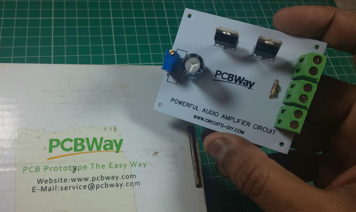
PCBWay commits to meeting the needs of its customers from different industries in terms of quality, delivery, cost-effectiveness, and any other demanding requests. As one of the most experienced PCB manufacturers in China. They pride themselves to be your best business partners as well as good friends in every aspect of your PCB needs.
Hardware Required
The following components are required to make Audio Amplifier Circuit
| S.no | Component | Value | Qty |
|---|---|---|---|
| 1. | Darlington pair Transistors | TIP122, TIP127 | 2 |
| 2. | Audio Jack | 3.5mm/male, female | 1 |
| 3. | Smartphone | – | 1 |
| 4. | Terminal block connectors | – | 2 |
| 5. | Loudspeaker | 8 Ohm | 1 |
| 6 | Potentiometer | 10K | 1 |
| 7. | Capacitor | 470uF | 1 |
| 8. | Resistor | 150K | 1 |
| 9. | Jumper Wires | – | As per need |
| 10. | DC Battery with clip | – | 1 |
TIP122 Pinout
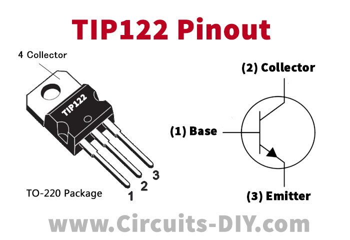
For a detailed description of pinout, dimension features, and specifications download the datasheet of TIP122
TIP127 Pinout
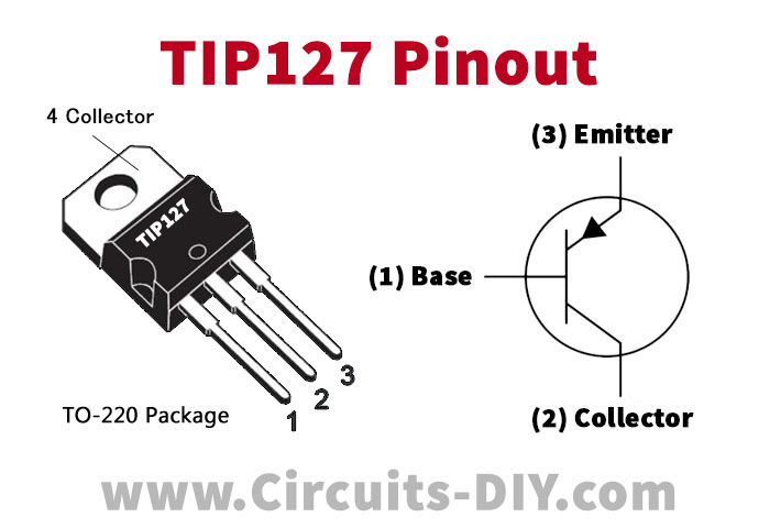
For a detailed description of pinout, dimension features, and specifications download the datasheet of TIP127
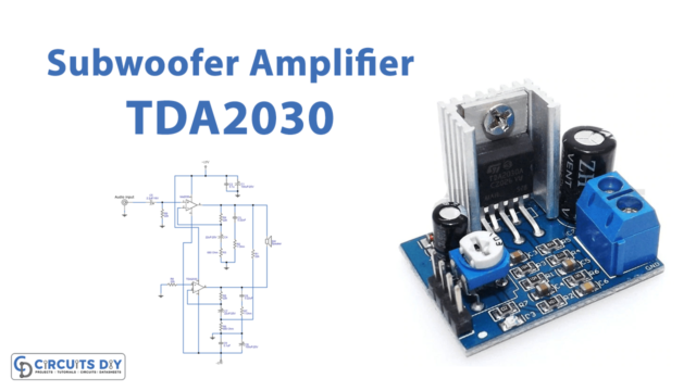
Audio Amplifier Circuit
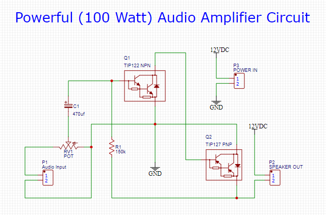
Working Explanation
The working of this circuit is as follows. The thing that makes this circuit unique is the robust & high-power TIP122/127 Darlington transistor pair. Audio input is taken from a general audio transducer such as a mic. This input acts as the DC control signal for the transistor Q1. Here, a capacitor (470uF) acts as a coupling capacitor, blocking the DC component of the signal, allowing only the AC component of the signal to pass through. Transistor Q1 amplifies the signal & sends it to the base of the transistor Q2.
The TIP127 further amplifies the input signal & directs it to an audio output device such as a loudspeaker. You can adjust the intensity of the output audio signal by simply tuning the 10K preset pot.