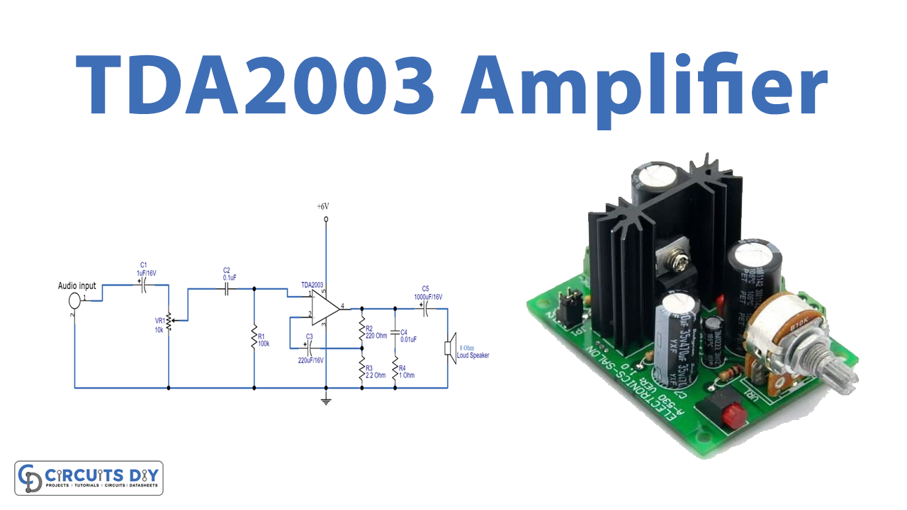
In this tutorial, we are going to make a “TDA2003 Amplifier Circuit Diagram”.
An audio power amplifier (or power amp) is an electronic amplifier that amplifies low-power electronic audio signals, such as the signal from a radio receiver or an electric guitar pickup, to a level that is high enough for driving loudspeakers or headphones. It is the final electronic stage in a typical audio playback chain before the signal is sent to the loudspeakers. Here we design an amplifier circuit with TDA2003 IC, it is a monolithic audio power amplifier integrated circuit that requires very low external components to operate as an amplifier.
This IC has only 5 pins and all are function pins, and it has built-in features like over-temperature protection and short circuit protection. It can handle short circuits in both AC & DC rails without damaging itself. It has an operating voltage of 18V but can handle high voltages up to 28V. This makes it robust to be used in automotive audio designs such as car stereos. By implementing this IC in a low-power audio amplifier, we can achieve the purpose of low harmonic and cross-over distortion, also it can provide high current output. We made this circuit for an 8Ω speaker, it can provide up to 10 watts of output, and you can power this circuit with a 6 to 12V power supply.
Hardware Required
| S.no | Component | Value | Qty |
|---|---|---|---|
| 1. | IC | TDA2003 | 1 |
| 2. | Variable Resistor | 10KΩ | 1 |
| 3. | Resistor | 100KΩ, 220Ω, 2.2Ω, 1Ω | 1,1,1,1 |
| 4. | Capacitor | 1uF/16V, 0.1uF, 220uF/16V, 0.01uF, 1000uF/16V | 1,1,1,1,1 |
| 5. | Speaker | – | 1 |
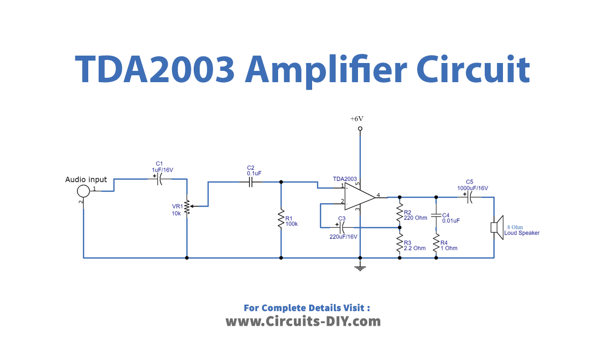
Circuit Diagram
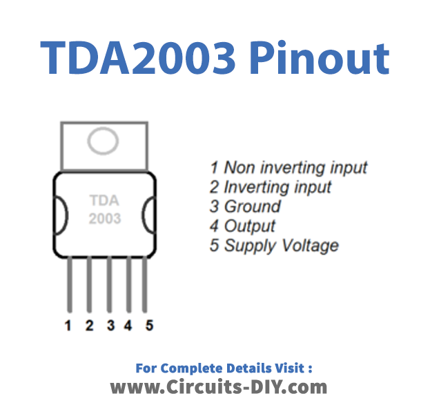
TDA2003 Pinout
Working Explanation
As we can see in the circuit, first connect the audio input signal to the non-inverting pin of the TDA2003 IC. Here VR1 acts as a volume control in this circuit. And inverting pin of the IC is connected with the C3 capacitor and R2, and R3 divider resistors to act as a feedback path, and the actual gain of the amplifier is set by the ratio of the R2 and R3 resistor. At the output, the loudspeaker is connected through a coupling capacitor. This TDA2003 amplifier can give up to 20 Watts output when connected in a bridge configuration. When we give the power supply 6V to the circuit. The C2 coupling audio signal by the VR1 adjusts the volume. The non-inverting amplifier circuit is a non-return phase. The signal output at pin 4 enhances the better stability of the low-frequency response by a C4. Another part of the output signal, which is fed back through C3 and R1 enters the pin 2 inverting, to maintain a constant frequency response. This TDA2003 IC can take supply voltage between 8 to 18 Volts and gives output power depending on load resistor RL, maximum 10 Watts if RL = 2Ω. It is sensitive to a minimum 14 mV input signal and provides an input resistance of 150KΩ. Refer datasheet for more electrical specifications.
Applications
- Used in audio automotive designs such as car stereos, radios & Hi-Fi audio setups.
- Widely used in sound systems such as speakers, high-power megaphones, & large-scale acoustic systems.
- An integral part of entertainment systems such as a home theatre setup.
- It can be used to cascade audio speakers.
- Also used for military applications such as acoustic weapons.