Introduction
An amplifier that is used to boost the input signal can be designed in different ways through different components. For this purpose, designers have also designed op-amp integrated circuits. But, one can also make amplifiers through the transistor. The transistor is a very basic electronic element. The component is essentially used in two modes. As a switch. And, an amplifier. In this circuit, we will use the transistor in amplification mode. So, in this article, we will learn how to make a Transistor Amplifier Circuit of 12 watts.
This circuit also uses the operational amplifier IC to get the required gain. Make sure to make the circuit on a good quality PCB board. Also, use the regulated and noise-free power supply. We have used the IC uA741. But, you can use any opamp that supports a 12V DC supply.
Hardware Components
The following components are required to make a 12 Watts Transistor Amplifier Circuit
| S.no | Component | Value | Qty |
|---|---|---|---|
| 1. | PCB board | – | 1 |
| 2. | IC | UA741 | 1 |
| 3. | Resistor | 1K, 20K, 47K, 270K | 2, 1, 2, 1 |
| 4. | Electrolytic Capacitor | 50pf | 1 |
| 5. | Transistor | AC108, 2N5294, 2N6107, BC178 | 1, 1, 1, 1 |
| 6. | Speaker | 4 ohms | 1 |
| 7. | Dual supply | 12V | 1 |
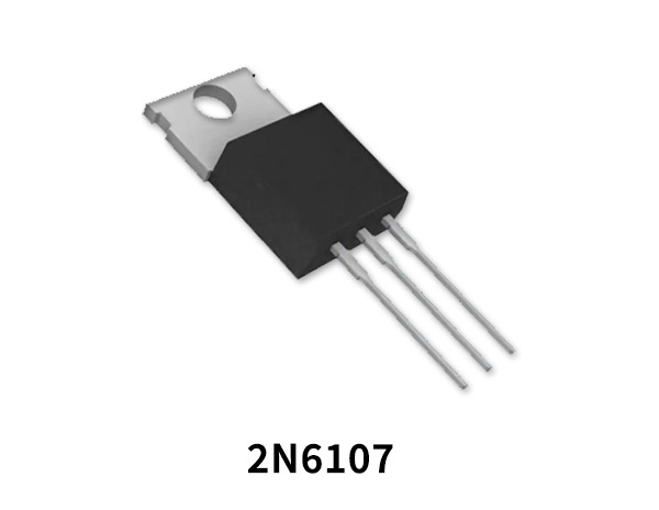
2N6107 Pinout
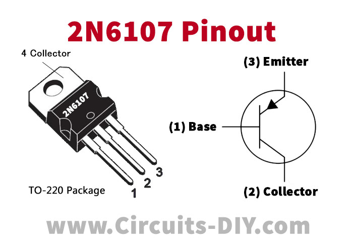
For a detailed description of pinout, dimension features, and specifications download the datasheet of 2N6107
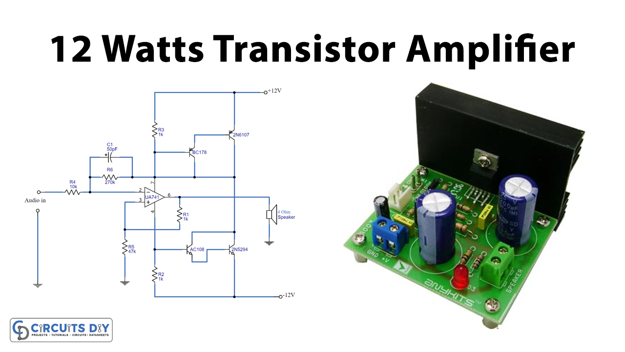
12 Watts Transistor Amplifier Circuit
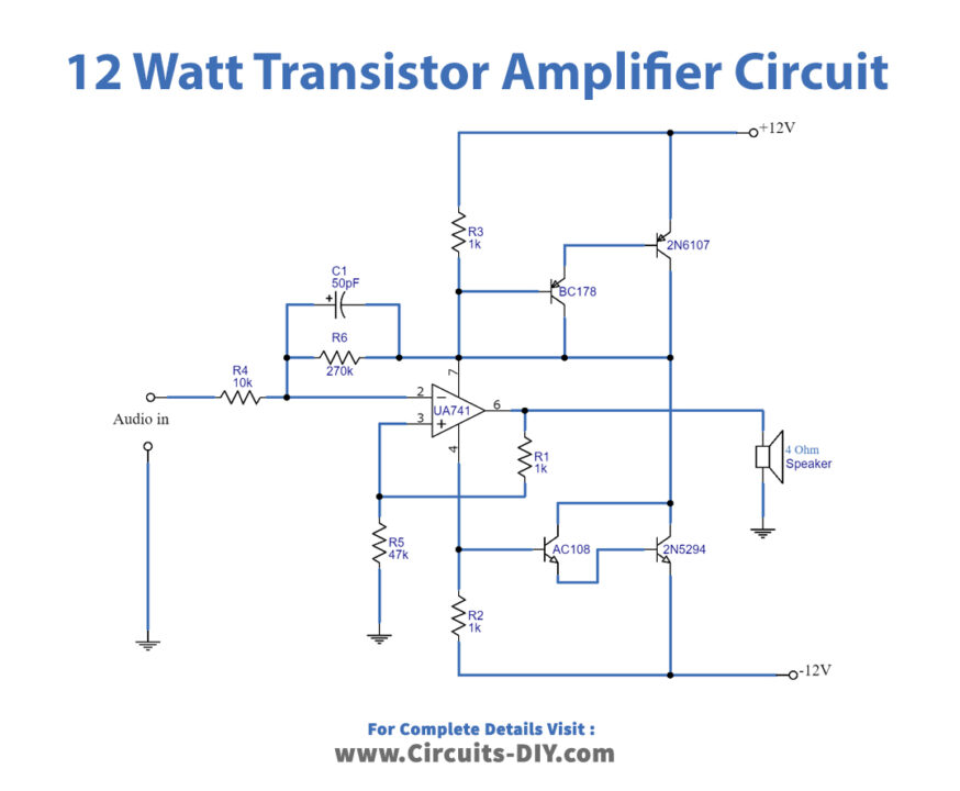
Working Explanation
In this transistor amplifier circuit, four transistors are connected as complementary to Darlington’s configuration to drive the load. Resistors R2 and R3 are the input resistors of Darlington’s pair. The voltage drop across these resistors is proportional to the input signal. The promising output having 12 volts of power would be generated across the four-ohm speaker.
Application and Uses
- For wireless circuits
- In optical fiber circuits
- For radio signal