In this tutorial, we are going to make a “Single Transistor Audio Amplifier Circuit”.
If your system has poor audio, it means that you have not used the proper audio amplifier for the system. An audio amplifier is an electronic circuit that amplifies low-power electronic audio signals to a level that is high enough for driving loudspeakers or headphones. we design a simple single transistor audio circuit without messy components only using BC547, Resistor, and Capacitor. Now single transistor amplifier can be made with three different configurations, common base, common collector, and the most widely used common emitter. Since the common emitter is extensively popular, therefore we will build a common emitter configuration.
Here Two types of single-transistor audio amplifier circuits are designed with BC547 transistors, the first one is for amplifying the direct audio signal and another one is for amplifying the audio signal from condenser MIC as a preamplifier. This circuit can drive an 8-ohm loudspeaker and produce considerable sound, for better results apply a 9 Volt DC supply.
Hardware Required
| S.no | Component | Value | Qty |
|---|---|---|---|
| 1 | Transistor NPN | BC547 | 2 |
| 2 | Resistor | 2KΩ,10KΩ, 2.2KΩ | 2,1,1 |
| 3 | Electrolytic Capacitor | 47µF/16V | 1 |
| 4 | Electrolytic Capacitor | 1µF/16V | 2 |
| 5 | Loud Speaker | – | 1 |
| 6 | Connecting Wires | – | – |
| 7 | Battery | 9V | 1 |
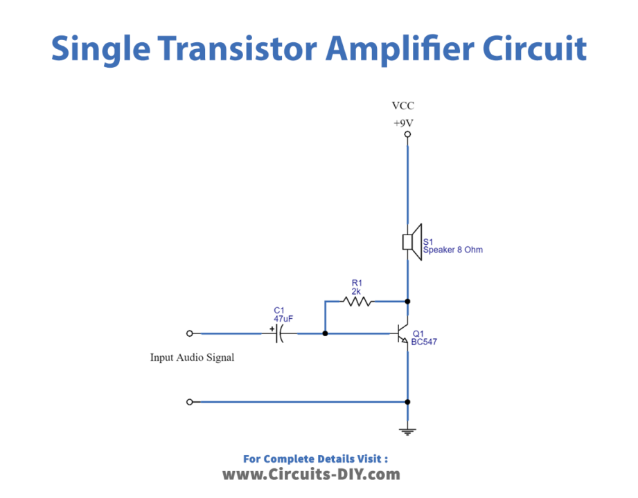
Circuit Diagram
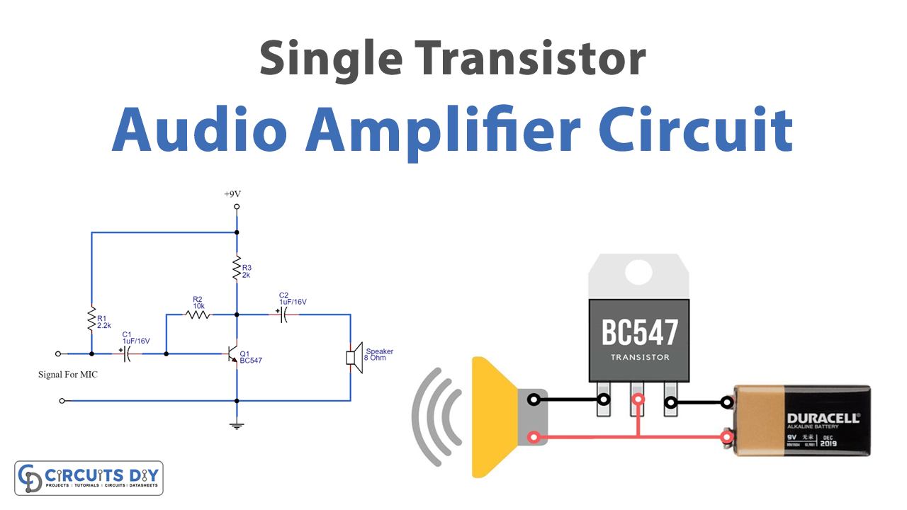
Pre Amplifier Circuit
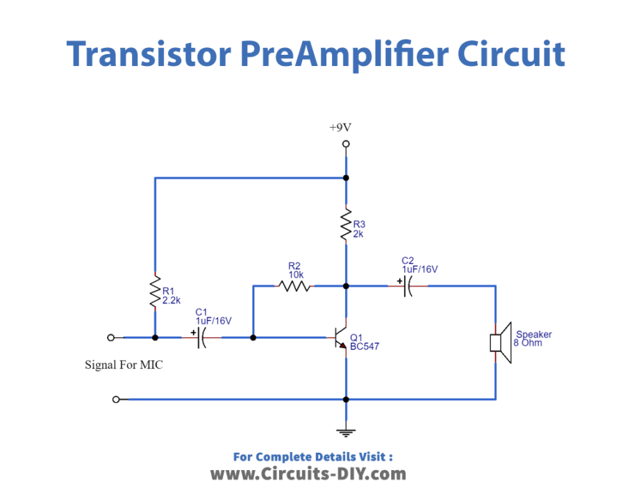
Working Explanation
To make an amplifier circuit start with Transistor BC 547 and connect proper bias to the Collector, Base, and Emitter terminals. As we have discussed earlier that we are using the Common-Emitter configuration, and therefore emitter is grounded, and we give a signal at the base of the transistor. Here for the first circuit, Loudspeaker is directly connected to the transistor collector terminal, and for the Preamplifier circuit speaker is connected through coupling capacitor C2.
When you provide the power supply of 9V to the circuit and give the weak input audio signal at the base of the transistor BC547 with the help of capacitor C1, and Collector coupled resistor R1, the current flows through the base. Hence enough audio signal and bias above cutoff voltage is constantly present at the base terminal of BC 547 and amplifies the input signal near peak Vcc. The amplified audio at the collector side works as the output side in this configuration. As a result, we get the amplified audio from the speaker wire at the collector as a load.
In the second circuit, to improve the audio signal we need to filter and amplify the input signal as the Input Audio signal is applied from the Condenser MIC and it may raw electric audio signal with distortion and noise in order. Here to strengthen the MIC signal R1 resistor is connected at the input to Vcc and C1 capacitor is used as a filter for removing distortion and coupling the audio signal to the transistor BC 547 Base. The output audio signal is received from the Collector terminal, here R2 acts as a Collector coupling resistor, and through the C2 capacitor is applied to Loud Speaker. we can take no phase shift audio signal by applying Bias above the cutoff to the transistor.
Applications
- Audio electronic devices.
- In Children’s Toys.
- For radio broadcasting.
- In microphone sound systems.